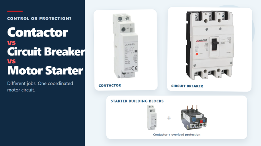
Figure 1. Contactors, circuit breakers, and motor starters solve different control and protection tasks.
These three devices often appear in the same motor-control panel, but they solve different problems. A contactor handles frequent, remote, or automatic switching during normal operation. A circuit breaker interrupts abnormal current within its rated capability. A motor starter normally combines a contactor with motor overload protection. In many motor-control circuits, they work together rather than compete.
This guide compares those functions, explains where a motor starter fits, and identifies the project information needed before choosing an industrial circuit breaker.
Quick Answer Control vs Protection
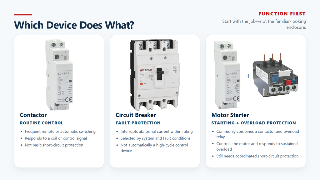
Start with function. A contactor repeatedly switches a load in response to a control signal. A circuit breaker interrupts abnormal current according to its protection design. A motor starter combines contactor-based switching with overload protection and still needs an appropriate short-circuit protection arrangement. One label is not a safe substitute for another.
Comparison point
Contactor
Circuit breaker
Motor starter
Main job
Routine load control
Circuit and equipment protection
Motor starting plus overload protection
Typical operation
Frequent start and stop commands
Trips during faults; opens for other duties when rated
Starts and stops a motor through its contactor
How it operates
Coil or electronic control signal
Trip mechanism, protective release, or manual operation
Contactor plus overload relay or equivalent protection
Short-circuit interruption
Not the job of a basic contactor
A primary function within the rated breaking capacity
Motor data, starter rating, contactor duty, overload range
Figure 2. Start with function: contactors control, circuit breakers protect, and motor starters combine switching with motor overload protection.
What a Contactor Does
A contactor is an electrically controlled switch. When the coil receives the correct control voltage, its magnetic mechanism changes the state of the main contacts and allows power to reach the load. Removing the control signal returns the contacts to their normal state.
This separates the control circuit from the load circuit. Push buttons, timers, relays, programmable logic controllers, and building-control systems can command a much larger load without carrying that load current themselves. The same principle makes contactors useful in motor starters, pumps, fans, compressors, conveyors, lighting banks, and HVAC equipment.
Current is one part of contactor selection. The designer must also confirm the load type, operating voltage, utilization category, expected switching frequency, coil voltage, starting current, ambient conditions, and required electrical life. A device suitable for a resistive load may be wrong for repeated motor starting at the same current.
A basic contactor does not replace short-circuit protection. Some products are sold as coordinated starters or assemblies that include an overload relay or electronic protection, but those additional functions belong to the assembly or added device. They should not be assumed from the word “contactor” alone. For a fuller explanation of the switching mechanism, see what a contactor is and how it works.
What a Circuit Breaker Does
A circuit breaker is a protective switching device. Its type and trip unit determine whether it detects or responds to overload current, short-circuit current, or other defined abnormal conditions before interrupting the circuit within its published ratings.
Breaker selection starts with the system, not the ampere label. The designer must confirm the voltage, AC or DC application, rated current, number of poles, available fault current, required breaking capacity, trip characteristics, coordination with upstream and downstream devices, and installation conditions. Do not approve a breaker from rated current alone.
Molded case circuit breakers serve industrial distribution, feeder protection, panel building, and selected motor-circuit applications. Thermal-magnetic models commonly combine overload and short-circuit response. Electronic trip units may add adjustable protection functions. In either case, the exact capability belongs to the selected series and model, not to the product category as a whole.
Although a breaker can be operated manually, its protective role does not automatically make it a substitute for a contactor. Frequent operational switching can impose a different duty from occasional manual operation or fault interruption. Use a breaker for routine switching only when the manufacturer explicitly rates the device for that application. You can review the basic protective mechanism in how a circuit breaker works.
What a Motor Starter Includes
A motor starter is an assembly, not another name for a contactor. A common magnetic starter combines a contactor for motor switching with an overload relay that responds to sustained overload conditions within its rating. The assembly may also include an enclosure, control buttons, auxiliary contacts, or other accessories.
This is the practical difference behind searches for motor starter vs contactor and contactor vs starter. The contactor is a key component inside the starter. The starter adds overload protection and supporting control functions, but it does not automatically provide adequate short-circuit interruption. Unless a selected protective assembly explicitly provides and verifies that function, the circuit still needs a coordinated breaker or fuse.
The term “starter motor” often refers to an automotive component, so it should not be confused with an industrial motor starter. In this article, motor starter means electrical equipment used to start, stop, and protect an industrial or commercial motor.
Contactor vs Circuit Breaker Comparison
Different Jobs in the Same Circuit
A contactor answers, ‘When should the load run?’ A circuit breaker answers, ‘What should open the circuit when current exceeds the permitted condition?’
Both devices contain contacts and both can interrupt current, which makes the comparison look simpler than it is. Their contacts, operating mechanisms, and arc-control systems are built for different duties. A contactor is optimized for commanded switching; a breaker is designed and rated to clear specified fault conditions.
Switching Frequency and Operating Life
Industrial equipment may start and stop many times during a shift. A correctly selected contactor is built for that repeated operational duty, and its coil provides a practical connection to interlocks, emergency-control logic, timers, sensors, and automation.
A circuit breaker normally operates far less often. It carries current continuously, responds to faults, and may provide an opening point when the selected device is suitable for isolation. Product ratings govern the permitted number and type of operations. There is no universal operation count: verify the manufacturer’s data for the exact model and duty.
Fault Interruption and Breaking Capacity
Breaking capacity can rule out a breaker even when its running-current rating looks correct. The device must interrupt the prospective fault current at the installation point under the applicable rating and conditions. If the available fault current exceeds that capability, matching the running current will not make the installation safe.
A contactor’s normal-load switching ability is not a short-circuit rating. Under high fault current, it may fail to interrupt safely, weld its contacts, or suffer severe damage. That is why the circuit needs upstream short-circuit protection.
Control Signals and Automation
The contactor coil connects the control system to the power circuit. A relatively small control signal can command a motor or other load, while auxiliary contacts report state or support interlocking.
Selected circuit breakers also accept accessories such as shunt trips, undervoltage releases, motor operators, and auxiliary contacts. These options support remote tripping, indication, or operation, but they do not make every breaker suitable for high-cycle switching. Confirm accessory compatibility and operating duty for the exact model.
Overload Protection Is a Separate Design Question
Short-circuit protection and motor overload protection address different events. A short circuit can produce very high current that must be interrupted rapidly. A motor overload may be lower in magnitude but persist long enough to overheat the motor. Treating both as the same selection question leaves a protection gap.
Some motor protection circuit breakers combine short-circuit protection with adjustable overload protection. Another common arrangement uses a circuit breaker or fuse for short-circuit protection, a contactor for switching, and an overload relay for motor overload protection. Choose between them from the motor, starting method, supply, control requirements, coordination data, and local rules.
Why Motor Circuits Often Need Both
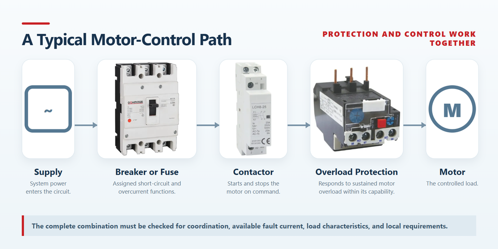
A common motor-control path assigns the functions in this order:
Supply → Circuit breaker or fuse → Contactor → Overload protection when required → Motor
Each element has a distinct job:
The upstream protective device interrupts short-circuit current and provides the overcurrent functions assigned by the design.
The contactor starts and stops the motor in response to control commands.
An overload relay or dedicated motor-protection function responds to sustained overload, stalled-rotor, phase-loss, or other conditions within its published capability.
The complete combination must be checked for coordination, available fault current, load characteristics, and applicable regional requirements.
Figure 3. A typical motor-control path assigns short-circuit protection, switching, and overload protection to separate coordinated functions.
Schneider Electric’s motor-protection guidance describes thermal-magnetic motor circuit breakers that provide short-circuit and overload protection, and it also shows systems that pair a magnetic breaker or fuse with a separate overload relay. ABB application guidance likewise treats contactor-controlled and circuit-breaker-controlled motors as distinct protection arrangements. Selecting one component does not remove the need to assign every required control and protection function.
For related product architecture, see the motor protection circuit breaker category. Final design and verification should be completed by qualified personnel. This article does not provide energized testing, bypass, or field-wiring instructions.
Which Device Do You Need
Buyer task
Likely functional arrangement
What still needs confirmation
Start and stop a motor remotely and frequently
Contactor plus appropriate protection
Motor data, start method, switching duty, coordination
Contactor and circuit breaker, with overload protection when required
Control voltage, load category, protection functions, coordination
Provide maintenance isolation
A device explicitly suitable for isolation
Isolation marking, lockout method, local requirements
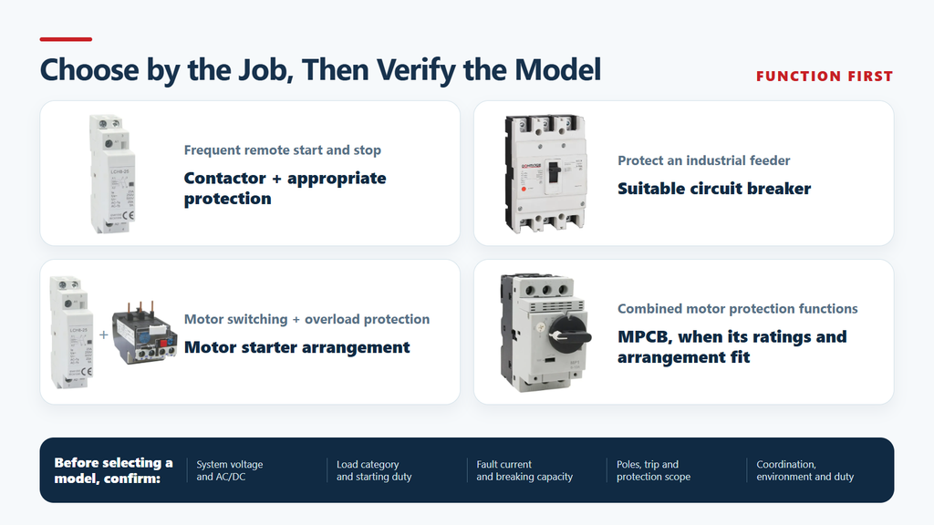
Figure 4. Choose the device category by the job, then verify the exact model against system, load, fault, and coordination data.
Use the table to identify which type of device belongs in the circuit. Do not use it to choose a model. That decision still requires project data and the manufacturer’s coordination information.
How to Specify the Circuit Breaker Side
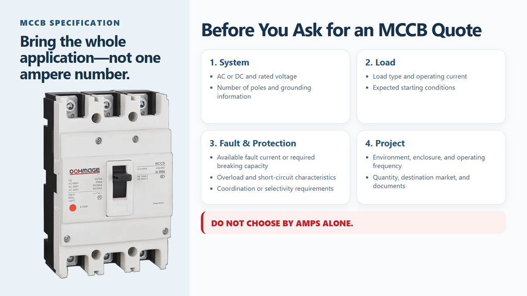
Before asking for an MCCB recommendation or quotation, prepare these inputs:
AC or DC system and rated voltage.
Load type, operating current, and expected starting conditions.
Required number of poles and relevant grounding-system information.
Available fault current at the installation point or required breaking capacity.
Required overload and short-circuit protection characteristics.
Upstream and downstream coordination or selectivity requirements.
Installation environment, enclosure conditions, and operating frequency.
Quantity, destination market, and required technical documents.
Figure 5. An MCCB quotation needs complete system, load, fault, protection, and project inputs—not current rating alone.
Do not request an MCCB from ampere rating alone. The full set of inputs lets the supplier compare thermal-magnetic, electronic, adjustable, and DC-rated options without extending one model’s capability to an entire product family. If critical project data is still missing, the model recommendation is not ready yet.
OOHMAGE publishes several MCCB series for industrial distribution and project-based selection. Review the molded case circuit breaker series and match the exact model’s published parameters to the project before ordering. Do not assume that a series fits because its current range looks close.
Common Mistakes
Using a Contactor as Short-Circuit Protection
A contactor can open a load during normal operation, but that gives it no circuit-breaker fault-interruption rating. The circuit still needs a suitable protective device.
Using a Breaker for Frequent Automatic Switching
Using a breaker like a contactor can exceed the duty intended for that device. Verify a specific switching rating, or use a contactor designed for the required operating cycle.
Confusing Overload and Short-Circuit Protection
Overload and short-circuit conditions both involve excessive current, but their magnitude, duration, and required response differ. A motor may need overload protection in addition to upstream short-circuit protection.
Selecting Only by Rated Current
Rated current is the starting point. Voltage, AC or DC suitability, load category, available fault current, breaking capacity, poles, trip behavior, and environmental conditions can each change the selection.
Assuming AC and DC Ratings Are Interchangeable
DC interruption places different demands on arc control. Use a model with published ratings for the actual DC voltage and pole arrangement. Do not transfer an AC rating by assumption.
Ignoring Coordination
A breaker, contactor, and overload relay must operate as one system. Check the manufacturer’s coordination data and local requirements; matching current labels do not prove that the combination is suitable.
Frequently Asked Questions
Can a Contactor Replace a Circuit Breaker
No. A basic contactor controls a load during normal operation; it is not a substitute for a circuit breaker or fuse selected to interrupt short-circuit current. Any circuit using a contactor still needs suitable upstream protection.
Can a Circuit Breaker Replace a Contactor
Usually not when the load requires frequent, remote, or automatic switching. A breaker may support manual operation, remote accessories, or defined switching duties, but the exact device and application must be rated for that use.
Why Is an Overload Relay Used with a Contactor
The contactor switches the motor. The overload relay monitors sustained current conditions that could overheat it and opens the control circuit when required. Short-circuit protection remains the job of a suitable breaker or fuse unless a coordinated device provides both functions.
Do All Motor Circuits Need Both Devices
No single arrangement fits every motor circuit. The required devices depend on motor power, starting method, supply, control needs, protection scheme, coordination data, and local rules. Many automated motor circuits use both a contactor and a protective device because switching and fault protection remain separate tasks.
What Information Is Needed for an MCCB Quotation
Provide the system voltage, AC or DC application, rated current, number of poles, required breaking capacity, protection method, load or application, quantity, installation conditions, and destination market. Select the model only after checking the published data for the proposed MCCB series.
Final Takeaway
A contactor controls normal operation. A circuit breaker protects against defined abnormal current conditions. Similar appearance in a panel does not make their ratings or responsibilities interchangeable. Many motor circuits therefore use a breaker or fuse for fault protection, a contactor for start-stop control, and an overload relay or dedicated motor-protection function where required.
Assign each function first, then select devices from verified project parameters. For the breaker side of an industrial panel, send the voltage, current, poles, required breaking capacity, application, quantity, and destination market through the OOHMAGE contact page. If an OOHMAGE series fits, the response should show why and identify the available technical documentation. If none fits, do not force the choice.
Introduction The concept of remote tripping is simple, but in actual operation, project teams often encounter difficulties in specifying the components. The panel factory may require circuit breakers triggered by fire alarm relays, PLC outputs, building management system instructions, or other coordinated control. At this point, “diversion tripping” is only the first step in the […]
The main types of circuit breakers used in low-voltage distribution include miniature circuit breakers (MCBs), molded case circuit breakers (MCCBs) and residual-current devices such as RCCBs and RCBOs. They are not interchangeable. MCBs and MCCBs are selected for overcurrent protection in different circuit roles, an RCCB provides residual-current protection without integral overcurrent protection, and an […]
Introduction The kA rating refers to the maximum short-circuit current that a circuit breaker can safely interrupt under specified conditions. For MCCB, this value constitutes a part of its interrupting capacity rather than its normal rated operating current. Choosing the correct kA rating helps to prevent the circuit breaker from malfunctioning when the fault current […]