Voltage Transformer vs Current Transformer: Definition, Working & Uses
Published: Author: Conor
Transformers are among the most important components in modern electrical systems. They make it possible to transmit, distribute, and measure electrical power safely and efficiently. While most people are familiar with large power transformers that step voltages up or down in the grid, instrument transformers—specifically the voltage transformer (VT) and the current transformer (CT)—play an equally critical role.
These specialized transformers are designed not to transfer bulk power, but to provide scaled-down and accurate representations of high voltages and currents. By doing so, they allow engineers, meters, and protection devices to safely monitor and control electrical networks. Understanding the differences between voltage Transformer vs current Transformer is essential for electrical engineers.
What Is a Voltage Transformer (VT)?
A Voltage Transformer (VT), often referred to as a Potential Transformer (PT), is a type of instrument transformer used to step down high system voltages into standardized, safer levels. Directly connecting measuring devices to high-voltage circuits would be both unsafe and impractical. By producing a proportional low-voltage output, the VT makes it possible to observe and analyze the electrical system without exposing instruments or personnel to danger.
In terms of construction, a voltage transformer resembles a scaled-down power transformer. Its primary winding, composed of many turns of wire, is connected across the high-voltage circuit. The secondary winding, with far fewer turns, provides the reduced output voltage. The device operates on the principle of electromagnetic induction, ensuring that the voltage ratio between primary and secondary remains precise. This accuracy is critical for applications in metering and protection.
Beyond measurement, VTs serve as an important isolation barrier. By separating high-voltage equipment from monitoring instruments, they enhance both safety and reliability. They are indispensable in a wide range of applications, from voltage monitoring in substations to feeding protective relays that guard against abnormal voltage conditions. In essence, the VT enables high-voltage systems to be managed safely, accurately, and efficiently.
Types of Voltage Transformers
Electromagnetic VT: Built with a laminated iron core and windings, typically used in medium-voltage systems.
Capacitive Voltage Transformer (CVT): Combines a capacitor divider with an inductive transformer, widely used in high-voltage and extra-high-voltage transmission lines for both metering and protection.
What Is a Current Transformer (CT)?
A Current Transformer (CT) is a specialized instrument transformer that reduces high-line currents to much smaller, standardized values suitable for measurement and protection. In high-voltage systems, currents can reach thousands of amperes—levels that would destroy ordinary meters and pose serious safety hazards. The CT solves this problem by delivering a proportional current signal, typically scaled down to 5 A or 1 A, allowing instruments and relays to operate safely and accurately.
The construction of a CT differs from that of a voltage transformer. Its primary winding usually has very few turns—sometimes it is nothing more than a single conductor carrying the line current. The secondary winding, on the other hand, consists of many turns of wire wound around a magnetic core. When current flows through the primary conductor, it generates a magnetic flux in the core, which in turn induces a proportional current in the secondary winding. This principle of electromagnetic induction ensures that the secondary output is a precise replica of the primary current, only scaled down to a usable level.
Current transformers are widely used in power systems for both measurement and protection. They feed ammeters and wattmeters in substations, supply data to protective relays for overcurrent or fault detection, and enable accurate monitoring of industrial equipment and motors. Because of their role in protection circuits, CTs are considered critical safety components. One important rule is that a CT’s secondary winding must never be left open-circuited while in service; doing so can cause dangerously high voltages to appear across the secondary terminals.
The CT is the indispensable counterpart to the voltage transformer: while the VT makes high-voltage measurement possible, the CT does the same for high currents, ensuring both safety and precision in electrical systems.
Types of Current Transformers
Bar-Type CT – Uses a bar conductor as the primary. Common in switchgear and busbar systems.
Wound CT – Has a dedicated primary winding. Offers high accuracy.
Toroidal CT – Has no primary winding; the conductor carrying current passes through a toroidal core.
Voltage Transformer vs Current Transformer: Key Differences
Though both are instrument transformers, their purposes, designs, and applications differ significantly.
Feature
Voltage Transformer (VT/PT)
Current Transformer (CT)
Purpose
Steps down high voltage to measurable levels
Steps down high current to measurable levels
Connection
Connected in parallel with the circuit
Connected in series with the circuit
Output
Standardized low voltage (e.g., 110 V)
Standardized low current (e.g., 5 A, 1 A)
Primary Winding
Many turns
Very few turns
Secondary Winding
Fewer turns
Many turns
Applications
Voltage metering, over/under voltage protection
Current metering, overcurrent and fault protection
Accuracy Focus
Voltage ratio & phase angle
Current ratio & phase angle
Working Principles Compared
Although VTs and CTs share the same foundation—Faraday’s law of electromagnetic induction—their designs and working principles diverge because one scales voltage and the other scales current.
Voltage Transformer (VT): Steps down high system voltage to a lower value for metering and protection. Operates under no-load conditions with high accuracy.
Current Transformer (CT): Steps down current, operating under load conditions. Must never be left open-circuited when energized, as this creates dangerously high voltages.
This distinction makes VTs and CTs complementary but non-interchangeable in power systems.
Applications of VT and CT
Applications of Voltage Transformers (VTs)
Voltage Measurement: Provide a scaled-down voltage for meters.
Relay Protection: Enable devices to detect abnormal voltages.
Synchronization: Ensure safe connection of generators to the grid.
Monitoring Systems: Used in SCADA and substation automation.
Applications of Current Transformers (CTs)
Energy Billing: Allow accurate measurement of consumer energy usage.
Protection Relays: Essential for overcurrent, earth fault, and differential protection.
Load Monitoring: Track power consumption trends.
Industrial Equipment Protection: Prevent damage by detecting abnormal current flow.
Together, VTs and CTs form the backbone of instrumentation and protection systems in power networks.
Common Mistakes and Safety Notes
Despite their importance, misuse of CTs and VTs can lead to serious hazards:
CT Open-Circuit Hazard: If a CT secondary is left open while carrying primary current, a dangerously high voltage develops across its terminals. This can damage equipment and pose a risk to personnel. Rule: CT secondary must always be shorted or connected to a burden.
VT Short-Circuit Hazard: A voltage transformer secondary must never be short-circuited, as this can cause excessive current and potentially damage the winding. Rule: VT secondary should always feed into appropriate burden or meter.
Incorrect Connections: Mixing up CT polarity or VT connections can lead to false readings and malfunction of protection relays.
Understanding and observing these precautions is essential for safe installation and operation.
Conclusion
Voltage transformers and current transformers may appear similar, but their functions are fundamentally different. A Voltage Transformer (VT) steps down high voltages to safe levels for measurement and protection, while a Current Transformer (CT) reduces high currents to manageable values.
Both devices are essential for modern power systems—ensuring safe monitoring, accurate metering, and reliable protection. Understanding their definitions, working principles, and applications helps engineers, technicians, and students make informed decisions in electrical design and maintenance.
OOHMAGE is committed to delivering insights and solutions that help professionals navigate the complexities of electrical equipment. If you’re looking to learn more about transformers, protective devices, or other critical electrical equipment, explore our resources or contact us today.
FAQs
What is the main difference between CT and VT?
A CT steps down current for safe measurement, while a VT steps down voltage.
Why is CT used in protection circuits?
Because CTs can detect abnormal current levels and supply that information to protective relays, enabling quick disconnection of faulty circuits.
Is a Potential Transformer the same as a Voltage Transformer?
Yes. A potential transformer (PT) is another name for a voltage transformer (VT).
Can CT and VT be used interchangeably?
No. A CT is designed for current scaling, while a VT is designed for voltage scaling. They serve distinct purposes.
What happens if a CT is left open-circuited?
Dangerous high voltages can appear across its secondary, risking damage to equipment and personnel. This is why CTs must always have a closed secondary circuit.
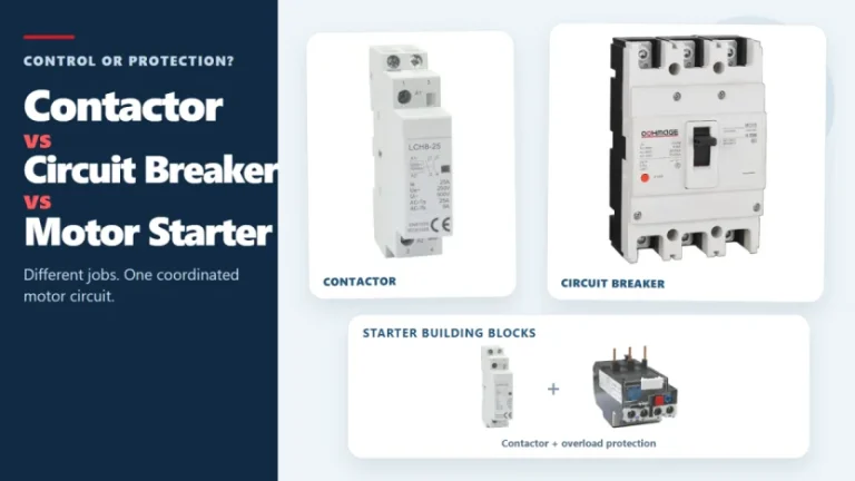
Figure 1. Contactors, circuit breakers, and motor starters solve different control and protection tasks. These three devices often appear in the same motor-control panel, but they solve different problems. A contactor handles frequent, remote, or automatic switching during normal operation. A circuit breaker interrupts abnormal current within its rated capability. A motor starter normally combines […]
The main types of circuit breakers used in low-voltage distribution include miniature circuit breakers (MCBs), molded case circuit breakers (MCCBs) and residual-current devices such as RCCBs and RCBOs. They are not interchangeable. MCBs and MCCBs are selected for overcurrent protection in different circuit roles, an RCCB provides residual-current protection without integral overcurrent protection, and an […]
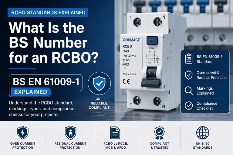
Introduction If you are searching for the RCBO BS number, the answer most commonly required in UK and IEC-based electrical procurement is BS EN 61009-1. This is the principal product standard associated with residual current circuit breakers with overcurrent protection used in residential, commercial, and similar installations. However, merely the BS number is not sufficient […]