The Engineering Challenge: Heavy industrial environments generate severe voltage surges and thermal loads that continuously degrade standard electrical infrastructure.
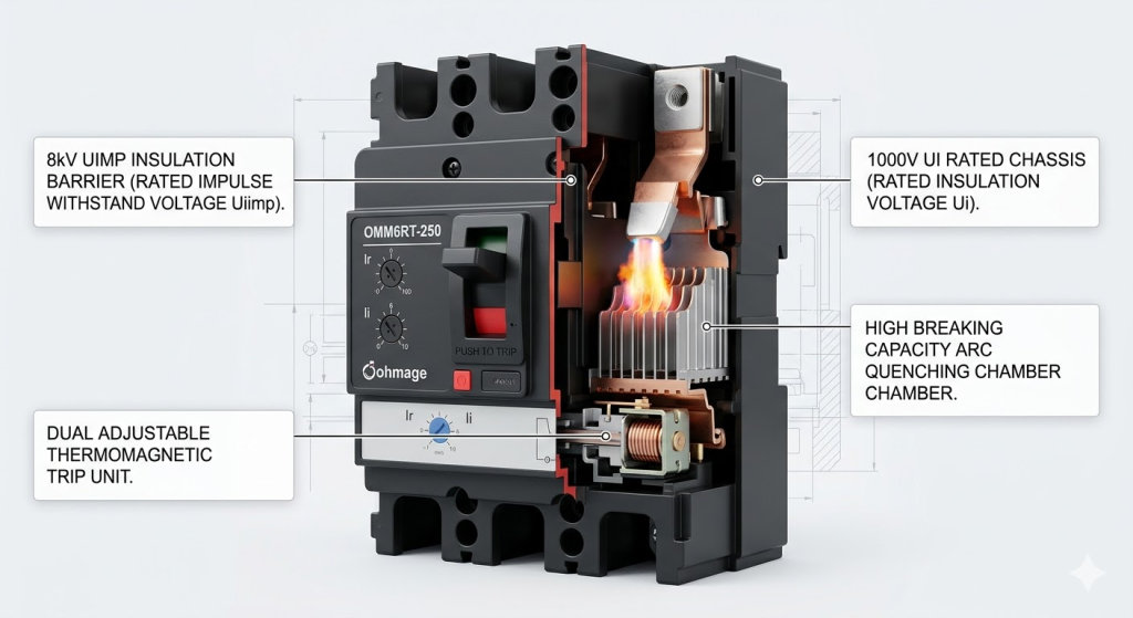
The Technical Standard: Modern facility resilience requires switchgear tested to an 8kV Impulse Withstand Voltage (Uimp) and a 1000V Insulation Voltage (Ui).
The Compliance Solution: Utilizing strictly IEC 60947-2 compliant Molded Case Circuit Breakers (MCCBs) ensures operational continuity and passes international site inspections.
The Realities of Industrial Power Distribution
Global manufacturing facilities operate under immense, continuous electrical stress. Heavy-load environments inherently generate unpredictable voltage surges throughout the production cycle. These transient electrical events constantly challenge the foundational integrity of the local power grid.
Back in 2005, our engineering teams at Oohmage began analyzing these exact industrial power challenges. We recognized early on that standard commercial switchgear struggles significantly in demanding factory settings. Consequently, modern infrastructure requires protective components explicitly engineered for extreme electrical parameters.
The Molded Case Circuit Breaker (MCCB) acts as the primary defense against catastrophic grid anomalies. Simply matching the required amperage is no longer sufficient for safe, modern facility design. Procurement teams must scrutinize international testing standards to identify truly resilient industrial assets.
Exploring specific electrotechnical ratings reveals exactly how engineers prevent expensive, immediate plant shutdowns. Objective data ultimately drives the safest purchasing decisions for global infrastructure projects.
The Physics of MCCB Breaking Capacity
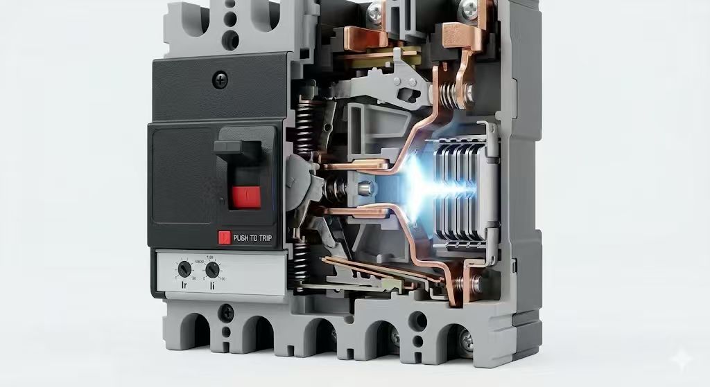
Interrupting a severe short circuit triggers a violent physical event inside the switchgear. Separating the internal copper contacts during a fault generates a massive, superheated plasma arc.
This uncontrolled electrical arc burns hot enough to vaporize surrounding metallic components almost instantly. True industrial-grade breakers utilize specialized magnetic arc chutes to manage this extreme thermal energy. These advanced chutes actively divide, stretch, and cool the plasma stream within milliseconds.
The overall efficiency of this rapid arc quenching completely defines the breaker’s ultimate safety limits. Devices failing to extinguish the arc immediately risk welding their internal contacts permanently closed. Such mechanical failures inevitably lead to severe electrical fires within the main distribution board.
International electrotechnical bodies provide rigorous testing frameworks to quantify this exact safety threshold. Understanding these vital metrics allows engineers to design incredibly safe, risk-averse power networks.
Icu vs. Ics: The IEC 60947-2 Benchmark
The global benchmark for industrial circuit breakers remains the stringent IEC 60947-2 standard. Within this comprehensive framework, engineers evaluate two distinct, yet heavily interrelated, breaking capacity metrics. Understanding the difference between these two numbers is crucial for facility longevity.
The Ultimate Short-Circuit Breaking Capacity (Icu) represents the absolute maximum fault a breaker can interrupt. While the device will safely clear an Icu-level event, it often sustains permanent internal damage afterwards. Facility managers must subsequently replace the compromised unit to restore total grid security.
Conversely, the Service Short-Circuit Breaking Capacity (Ics) indicates the fault current a breaker can clear repeatedly. Achieving an Ics value equal to 100% of the Icu means the device repeatedly survives maximum faults. This specific performance ratio acts as a proven statistical indicator of profound mechanical longevity.
Choosing a breaker with a flawless Ics ratio significantly reduces expensive, emergency maintenance interventions. Heavy industries rely on this metric to guarantee continuous production across multiple operating shifts.
Transient Overvoltages and the 8kV Uimp Standard
Industrial plants face unique electrical challenges extending far beyond simple short circuits. Starting large robotic motors and switching inductive loads constantly generate severe transient overvoltages. These sudden electrical spikes travel rapidly backwards through the grid.
Transient surges directly attack the switchgear’s internal insulation materials. Standard commercial breakers generally offer a modest 6kV Rated Impulse Withstand Voltage (Uimp). Empirical laboratory testing shows this specific threshold frequently fails in Overvoltage Category III installations.
Industrial facilities absolutely require much higher resilience to survive standard 1.2/50 µs transient surge waveforms. Upgrading the main distribution board to an 8kV Uimp standard provides a massive safety buffer. This elevated technical rating ensures that routine inductive switching will not cause catastrophic dielectric breakdown.
Combating Thermal Degradation with 1000V Ui
Continuous operational heat relentlessly degrades internal plastics over years of active service. Operating high-amperage equipment within a confined distribution board generates inescapable thermal stress. Ambient factory dust and high atmospheric humidity heavily accelerate this material degradation.
Over time, these combined environmental factors inevitably lead to dangerous carbon tracking across the chassis. Engineers carefully analyze the Rated Insulation Voltage (Ui) to combat this creeping vulnerability effectively. This specific metric defines the true, long-term dielectric strength of the molded materials.
Furthermore, the Ui rating determines the minimum internal creepage distances required for safe operation. Specifying a rigorous 1000V Ui rating virtually eliminates hidden long-term arcing risks. High-insulation industrial plastics easily endure decades of continuous thermal punishment while maintaining absolute integrity.
The Role of Advanced Trip Units
The internal tripping mechanism dictates exactly how the breaker responds to different network anomalies. Traditional thermal-magnetic units utilize a bending bimetallic strip for overloads and a magnetic coil for short circuits. These classic mechanisms provide incredibly reliable protection for standard, highly predictable industrial loads.
Their relatively simple, rugged construction makes them highly immune to complex electromagnetic interference. Alternatively, modern electronic trip units use integrated microprocessors to measure current flow with digital precision. These intelligent devices allow engineers to program highly specific tripping curves and exact time delays.
Electronic units truly excel in complex environments requiring intricate coordination between multiple panel boards. Their programmable precision ensures that massive distribution networks isolate electrical faults perfectly every single time. Choosing the correct trip unit remains a fundamental step in comprehensive grid design.
Coordinating Industrial Distribution Networks
Protecting a large manufacturing facility requires a highly coordinated approach to fault management. A localized short circuit on a minor assembly line must never trigger the main utility breaker. Achieving total selectivity demands a careful combination of specific frame sizes and adjustable trip units.
A massive automotive plant might utilize a robust 2000A MCCB at the utility intake. Further downstream, smaller 250A breakers efficiently protect the individual robotic welding stations. By expertly tuning the tripping thresholds, technicians ensure only the breaker closest to the fault activates.
This meticulous precision completely isolates the dangerous anomaly while keeping the rest of the factory online. Coordinate protection strategies represent the pinnacle of professional electrical engineering in large-scale infrastructure.
Supply Chain Agility and Total Cost of Ownership
Procurement teams sometimes prioritize the lowest initial sticker price over robust technical specifications. This strictly financial approach frequently backfires spectacularly in demanding, high-load industrial settings. Standard commercial breakers fail rapidly under the severe mechanical stress of continuous manufacturing cycles.
Unplanned factory downtime costs major facilities thousands of dollars per minute. Stalling a major infrastructure build while waiting for backordered switchgear destroys project profitability entirely. Partnering directly with a certified ODM/OEM shared manufacturer eliminates these costly logistical bottlenecks.
Reliable, immediate access to correctly rated, thoroughly tested switchgear forms the foundation of any successful build. Visitors to oohmage.com frequently utilize our technical datasheets to verify these performance metrics before ordering. Transparent engineering data always builds the strongest long-term procurement partnerships.
Frequently Asked Questions (FAQ)
What is the functional difference between an MCB and an MCCB? Miniature Circuit Breakers (MCBs) typically handle continuous currents up to 125A for commercial sub-distribution. Molded Case Circuit Breakers (MCCBs) manage massive loads up to 2000A and provide adjustable trip settings.
Why is IEC 60947-2 compliance strictly necessary? This international standard objectively verifies that the circuit breaker safely interrupts high fault currents. Utilizing non-compliant switchgear poses a severe liability risk and guarantees failed modern facility inspections.
Can engineers use a 690V Ui rated breaker in heavy industry? We generally advise against this practice in highly polluted or thermally intense environments. Heavy industrial plants require a minimum Rated Insulation Voltage (Ui) of 1000V to prevent surface arcing entirely.
How does altitude affect MCCB performance? Installations in mountainous regions face lower air density, which negatively affects natural cooling capabilities. Engineers must apply specific derating factors to the breaker’s operational limits at higher altitudes.
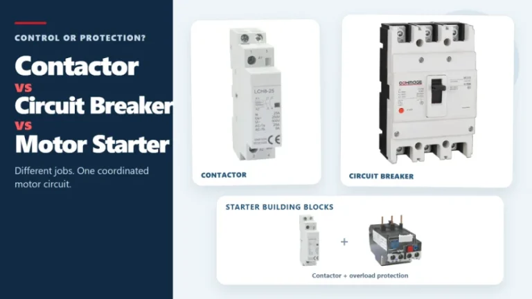
Figure 1. Contactors, circuit breakers, and motor starters solve different control and protection tasks. These three devices often appear in the same motor-control panel, but they solve different problems. A contactor handles frequent, remote, or automatic switching during normal operation. A circuit breaker interrupts abnormal current within its rated capability. A motor starter normally combines […]
The main types of circuit breakers used in low-voltage distribution include miniature circuit breakers (MCBs), molded case circuit breakers (MCCBs) and residual-current devices such as RCCBs and RCBOs. They are not interchangeable. MCBs and MCCBs are selected for overcurrent protection in different circuit roles, an RCCB provides residual-current protection without integral overcurrent protection, and an […]
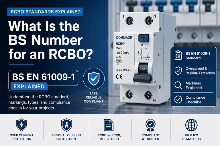
Introduction If you are searching for the RCBO BS number, the answer most commonly required in UK and IEC-based electrical procurement is BS EN 61009-1. This is the principal product standard associated with residual current circuit breakers with overcurrent protection used in residential, commercial, and similar installations. However, merely the BS number is not sufficient […]