Ring Main Unit Basics: What It Is and How It Works in Power Distribution
Published: Author: Conor
Today‘selectricitysupplymust be extremelyreliable and secure. Power outages are not justa hassle; they can meancostly downtime for manufacturing industries, safety hazards for public buildings, and inconveniences for household communities. For utilities and facility operators, the challenge is to maintain a steady supply even when part of the network experiences a fault.
One of the key technologies enabling this reliability is the Ring Main Unit (RMU). Compact yet capable, RMUs play a vital role in medium-voltage (MV) power distribution systems, ensuring that faults can be isolated without shutting down the entire network.
This article takes a closer look at what RMUs are, how they operate, their key components, types, applications, and the factors to consider when selecting one.
What Is a Ring Main Unit (RMU)?
Illustration of OOHMAGE’s GIS Ring Main Unit
A Ring Main Unit is a type of medium-voltage switchgear designed to be part of a looped distribution network. Power in a ring systemcan be supplied from eitherdirection. When one side is severed—due to fault or maintenance—the other maycontinue tosupply the load.
Key functions include:
Switching– Safely turning sections of the network on or off under normal load conditions.
Isolation– Disconnecting faulty sections to prevent damage and allow maintenance.
Protection– Interrupting fault currents via circuit breakers or fuses.
Unlike conventional radial distribution, where a single fault can cut off power to an entire section, an RMU-based ring network minimizes outages, making it a preferred choice in urban networks, industrial estates, and renewable energy projects.
What Is the Power Distribution System?
To appreciate the RMU’s role, it’s important to understand the electricity supply chain:
Generation– Power is produced at plants (thermal, hydro, nuclear, wind, solar) at voltages typically between 10–25 kV.
Transmission– Voltage is stepped up (often 110–765 kV) for long-distance transport.
Sub-Transmission & Distribution– At primary substations, voltage is reduced to medium-voltage (commonly 11, 22, or 33 kV) for regional distribution.
Final Delivery– Distribution transformers step down voltage to 230/400 V for consumers.
The RMU is installed at the medium-voltage stage, typically between the primary substation and distribution transformers. It isusedin a looped feeder network, allowing electricity to take multiple paths to reach consumers.
Example: In a city block with underground cables, RMUs in roadside kiosks connect various buildings. If a cable is damaged during excavation, the RMU isolates that section and supplies the area from the alternate feeder, avoiding a blackout.
Key Components of an RMU
An RMU is a self-contained, modular switchgear unit, with each part designed for a specific role in switching, isolation, and protection.
Load Break Switch (LBS)
Function: Switches circuits under load safely without excessive arcing.
Design: Often spring-operated for fast, reliable action.
Arc Extinction Medium: SF₆ gas, vacuum, or air.
Use Case: Routine load switching and isolating feeders during maintenance without cutting total supply.
Illustration of OOHMAGE’s MCB Miniature Circuit Breaker
Relays– Detect faults and trigger tripping.
Fuses– Provide fast-acting protection for smaller feeders.
Earthing Switches– Ground circuits for maintenance safety.
Insulation & Arc-Quenching Medium
The insulation and arc-quenching medium in an RMU determines its size, performance, and environmental profile.
SF₆ Gas– Offers exceptional dielectric strength and arc-quenching efficiency, enabling compact, sealed designs ideal for space-constrained sites. However, SF₆ is a potent greenhouse gas with a high Global Warming Potential (GWP). Handling, filling, or recycling SF₆ requires trained and certified personnel, as many regions have strict environmental regulations governing its use. Utilities and manufacturers are increasingly exploring SF₆-free alternatives to meet sustainability targets.
Air– Low environmental impact but requires more space.
Solid Dielectric– Eco-friendly and maintenance-free, suitable for modern urban installations.
Enclosure
Material: Galvanized steel, stainless steel, or aluminum.
Ingress Protection (IP): IP54 or higher for dust/moisture resistance.
Arc Resistance: Arc-proof designs protect operators from arc flash hazards.
Control and Communication Modules
Enable remote operation via SCADA or Distribution Management Systems (DMS).
Provide real-time monitoring of load, voltage, and breaker status.
Support fault logging and analytics for predictive maintenance.
How a Ring Main Unit Works
An RMU operates in a looped feeder system, where power can circulate from two sources. In this arrangement, power is able to be rerouted in the event that a portion of it fails. Here’s how it does it in four stages:
Normal Operation – Electricity flows into the network from both Feeder A and Feeder B. Each RMU passes power along, so consumers receive electricity through either route. This redundancy means that both paths are active and available at all times.
Fault Occurrence – Whenever a fault between two RMUs happens (e.g., cable break). Protective relays detect it instantaneously. The RMUs close to the fault end automatically open their circuit breakers or switches and isolate only the damaged part.
Continued Supply – Even when the faulty segment is cut off, the rest of the loop remains powered by the second feeder. Customers largely never get disconnected, as power simply follows the other route around the loop.
Restoration – When repair work is finished, opened switches are reclosed by operators, reconnecting the loop in such a way that both feeders supply the network again. The system regains full redundancy.
Example: In an underground metro, a fault in one cable section is detected and isolated automatically. Escalators, lighting, and signals continue to be supplied from the standby path, without having to wait for crews to arrive.
Advanced RMUs integrated with SCADA can achieve all this remotely in seconds, reducing outage duration by a substantial margin.
Types of Ring Main Units
By Insulation
Gas-Insulated (SF₆)– Compact and reliable but faces environmental concerns due to greenhouse gas potential.
Air-Insulated– Larger and more affected by environmental conditions but avoids SF₆ issues.
Solid-Insulated– Eco-friendly, compact, and suitable for urban applications.
By Configuration
Extensible– Can be expanded to accommodate more feeders in the future.
Non-Extensible– Fixed number of feeders, more compact.
By Operation
Manual– Operated directly on-site.
Motorized– Allows remote control but still requires manual backup.
Fully Automated / Smart RMUs – Integrated into digital grids for real-time control.
Applications of RMUs in Power Distribution
Urban Networks
Installed in roadside kiosks or building basements.
Handles underground cables feeding office towers, malls, and residential complexes.
Minimizes visual impact compared to open-air switchgear.
Industrial Facilities
Protects sensitive loads in manufacturing plants.
Ensures production continues even if one feeder fails.
Reduced Maintenance– Many are “sealed for life”, minimizing service needs.
Fast Fault Isolation– Shortens outage times and improves customer satisfaction.
Scalability– Extensible designs support network growth.
Smart Integration– Digital RMUs enable real-time monitoring and predictive maintenance.
Key Considerations When Choosing an RMU
When selecting an RMU, assess:
Criterion
Why It Matters
Voltage & Current Ratings
Must meet network specs to prevent overload.
Insulation Type
Impacts size, cost, and environmental compliance.
Extensibility
Supports future capacity upgrades.
Compliance Standards
IEC/IEEE compliance ensures interoperability and safety.
Automation Capability
Enables integration into SCADA or IoT systems.
Environmental Conditions
Choose enclosures suited to indoor/outdoor use, humidity, or corrosive environments.
Evaluating these factors will help ensure you choose an RMU that delivers reliability today while supporting future network demands.
Maintenance Best Practices
Preventive Maintenance
Inspect enclosures for corrosion or leaks.
Test the operation of load break switches and breakers.
Check SF₆ pressure and top up if necessary.
Clean and tighten connections.
Condition Monitoring
Use thermal imaging to detect hot spots.
Monitor partial discharge levels in insulation.
Corrective Maintenance
Replace worn or faulty components.
Update control software in automated RMUs.
Tip: Even “maintenance-free” RMUs benefit from annual visual and functional checks to ensure reliability.
FAQs
Q1: What is the difference between RMU and switchgear?
While both RMUs and traditional switchgear are used for switching and protection in electrical networks, their configurations and applications differ:
Switchgear is a broad term covering all devices that control, protect, and isolate electrical circuits. It can be used in radial or ring networks and includes equipment such as circuit breakers, contactors, and disconnectors.
RMUs are a specific type of switchgear designed for ring (looped) networks. They are compact, sealed units with multiple load break switches and/or circuit breakers, enabling continuous power flow even if one feeder is offline.
Example: A utility may use large open-type switchgear in a substation for incoming feeders but deploy RMUs in roadside kiosks to connect urban underground cable loops for resilience.
Q2: What are the main maintenance tasks for an RMU?
While maintenance requirements vary, common tasks include:
Visual inspections– Checking for enclosure integrity, corrosion, or unusual smells (indicating overheating).
Gas pressure checks– Ensuring SF₆ levels are within limits.
Functional testing– Operating switches and circuit breakers to confirm mechanical integrity.
Relay calibration– Ensuring protection systems respond correctly.
Tip: Condition monitoring technologies, such as thermal imaging and partial discharge sensors, can help predict issues before they lead to outages.
Q3: Can RMUs be used for renewable energy projects?
Yes. RMUs are increasingly used in renewable energy integration, such as:
Solar farms– Connecting arrays to medium-voltage feeders while isolating faults without disrupting generation.
Wind farms– Managing multiple turbine feeders and providing fault protection.
Hybrid systems– Combining grid supply with distributed generation.
Their compact footprint and reliability make them ideal for remote renewable installations where downtime can be costly.
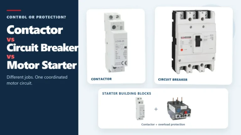
Figure 1. Contactors, circuit breakers, and motor starters solve different control and protection tasks. These three devices often appear in the same motor-control panel, but they solve different problems. A contactor handles frequent, remote, or automatic switching during normal operation. A circuit breaker interrupts abnormal current within its rated capability. A motor starter normally combines […]
The main types of circuit breakers used in low-voltage distribution include miniature circuit breakers (MCBs), molded case circuit breakers (MCCBs) and residual-current devices such as RCCBs and RCBOs. They are not interchangeable. MCBs and MCCBs are selected for overcurrent protection in different circuit roles, an RCCB provides residual-current protection without integral overcurrent protection, and an […]
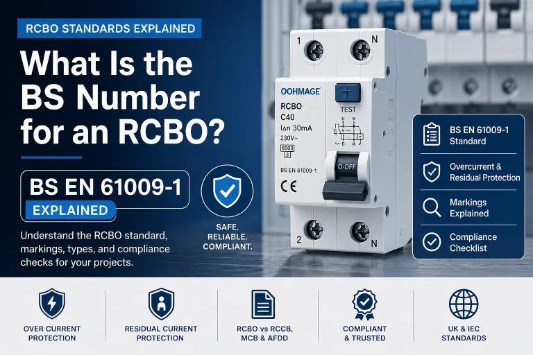
Introduction If you are searching for the RCBO BS number, the answer most commonly required in UK and IEC-based electrical procurement is BS EN 61009-1. This is the principal product standard associated with residual current circuit breakers with overcurrent protection used in residential, commercial, and similar installations. However, merely the BS number is not sufficient […]