Step-by-Step Guide to Wiring a Circuit Breaker Safely
Published: Author: Conor
Circuit breakers are essential components of any electrical system, protecting circuits from overloads and short circuits. Properly connecting wires to a circuit breaker is crucial to ensure not only the functionality of your electrical system but also your personal safety. While wiring a breaker may seem straightforward, incorrect connections can result in electrical hazards, damaged equipment, or even fire. This guide about wiring a circuit breaker is intended for educational purposes. Always follow local electrical codes, and if you are unsure, hire a licensed electrician.
Understanding Circuit Breakers
Before connecting any wires, it’s essential to understand what a circuit breaker (such as aminiature circuit breaker) is, how it functions, and the basics of connecting it safely. A circuit breaker is an automatic switch designed to interrupt the flow of electricity when it detects overloads or short circuits. Unlike fuses, which need to be replaced after they blow, circuit breakers can be reset and reused, making them more convenient for modern electrical systems.
Circuit breakers come in several types, each suited to different applications:
Breaker Type
Voltage
Typical Use
Single-Pole
120V
Standard household outlets and lighting circuits
Double-Pole
240V
Large appliances such as ovens, dryers, and HVAC units
GFCI (Ground Fault Circuit Interrupter)
120V
Kitchens, bathrooms, outdoor circuits—protects against ground faults
AFCI (Arc Fault Circuit Interrupter)
120V
Detects dangerous arcing conditions to prevent fires
Understanding the type of breaker you are working with ensures proper wiring and safety. For instance, a GFCI breaker is required in areas where water is present, whereas an AFCI breaker provides protection against arc-related hazards.
Circuit Breaker Connection Basics
Even before starting the installation, it’s helpful to understand the key elements of a typical breaker connection:
Line vs. Load Terminals
The line terminals receive power from the main panel, while the load terminals deliver power to the connected circuit. Connecting wires to the correct terminals is crucial for proper operation.
Hot, Neutral, and Ground Wires
Hot wires (usually black or red) carry electricity to your devices.
Neutral wires (white) return electricity to the panel.
Ground wires (bare copper or green) provide a safe path for stray electricity.
Compatibility and Ratings
Always ensure the breaker matches the panel type, voltage, and amperage requirements of your circuit. Using the wrong breaker can cause tripping or overheating.
Code Compliance
Local electrical codes may dictate which type of breaker or connection method is required. Always follow manufacturer instructions and regulations.
Tools and Materials Needed
Having the right tools and materials before starting is critical for both safety and efficiency. Here’s what you’ll need:
Tools:
Insulated screwdrivers
Wire strippers
Needle-nose pliers
Voltage tester or multimeter
Electrical tape
Flashlight (if working in a dim panel)
Materials:
Circuit breaker compatible with your electrical panel
Correct gauge wire (refer to your breaker’s rating)
Wire connectors or terminals (if necessary)
Safety Gear (optional but recommended):
Insulated gloves
Safety glasses
Protective clothing
Proper preparation reduces the risk of accidents and ensures the wiring process goes smoothly.
Safety Precautions Before You Start
Working with electricity can be dangerous, so safety precautions are non-negotiable. Always follow these steps:
Turn off the main power supply: Before opening the panel, switch off the main breaker to cut power to the entire system.
Verify with a voltage tester: Double-check that no live current is present before touching wires or terminals.
Use protective equipment: Insulated gloves and safety glasses help prevent electric shock and injury.
Work in a dry environment: Moisture can increase the risk of electrical hazards.
Follow local electrical codes: Ensure your work complies with regulations to avoid fines and hazards.
Taking these precautions reduces the risk of electrical shock and ensures a safer working environment.
Step-by-Step to Wiring a Circuit Breaker
Installing a circuit breaker safely involves careful preparation, precise connections, and strict adherence to safety guidelines. Follow these steps to ensure a reliable and secure installation:
Step 1: Cut Off the Main Power
Before touching any wiring, switch off the main breaker to disconnect power from the entire panel. Verify that the power is off using a voltage tester. Never work on live circuits—always double-check to prevent electric shock.
Step 2: Remove the Panel Cover
Carefully unscrew and lift off the panel cover. Be mindful that some components, like service lugs at the top of the panel, may still carry voltage even when the main breaker is off. Place the cover in a safe spot to avoid damage.
Step 3: Select the Correct Breaker Slot
Identify the slot where the new breaker will be installed:
Single-pole breakers occupy one slot and are used for standard 120V circuits.
Double-pole breakers take two adjacent slots for 240V circuits.
Make sure the breaker is compatible with your panel model and that the chosen slot is unoccupied.
Step 4: Prepare Your Wires
Choose the proper wire gauge according to the amperage rating of your breaker:
Breaker Amperage
Recommended Wire Gauge (AWG)
20A
12 AWG
30A
10 AWG
50A
6 AWG
Strip about ¾ inch of insulation from each wire end. Ensure the exposed copper is straight, clean, and free of nicks to allow a strong connection.
Step 5: Route the Wires Through the Panel
Feed your wires into the panel using an appropriate knockout hole. Secure the wires with a clamp or connector to prevent movement. Leave enough slack to work comfortably, but avoid excessive loops that can clutter the panel and make future maintenance difficult.
Step 6: Connect the Ground Wire
Attach the bare or green ground wire to the grounding bus bar. Tighten the screw securely so the connection is firm. The ground wire provides a safe path for stray electricity, helping prevent shocks or equipment damage.
Step 7: Connect the Neutral Wire (for 120V Circuits)
For standard 120V circuits, connect the white neutral wire to the neutral bus bar. Some 240V circuits may not require a neutral wire, depending on design and code. Always consult the breaker manufacturer’s instructions and local electrical regulations.
Step 8: Connect the Hot Wire(s)
Single-pole (120V): Insert the hot wire (black or red) into the breaker terminal and tighten the screw firmly.
Double-pole (240V): Connect both hot wires (typically black and red) to the breaker terminals.
After securing the screws, gently tug each wire to confirm it is firmly in place.
Step 9: Install the Breaker into the Panel
Snap the breaker into its designated slot. Ensure it is properly aligned and fully seated with the other breakers. At this point, the breaker is installed but still unpowered.
Step 10: Restore Power and Verify
Replace the panel cover and screw it securely in place.
Turn the main breaker back on.
Switch on the newly installed breaker.
Test the circuit with a voltage tester or by turning on a light or appliance to confirm that power is flowing correctly.
Additional Tips for a Safe Installation
Keep wires organized inside the panel using gentle loops to avoid tangling.
Avoid leaving exposed copper outside the terminals — this can lead to accidental contact and short circuits.
Always follow the manufacturer’s instructions for the specific breaker model.
If unsure at any point, don’t hesitate to consult a licensed electrician.
Common Mistakes to Avoid
Even experienced DIYers can make mistakes. Avoid these common errors:
Over-tightening or under-tightening screws: Can lead to loose connections or damaged terminals.
Confusing line and load terminals: Connecting wires incorrectly can prevent the breaker from working.
Using the wrong wire gauge: A wire too thin for the breaker can overheat and cause fire hazards.
Skipping safety checks: Always verify the power is off before touching wires.
Ignoring local codes: Non-compliance can be dangerous and illegal.
Being aware of these mistakes helps prevent accidents and ensures a durable electrical setup.
Tips for Long-Term Safety and Maintenance
Proper wiring is only part of the equation. Long-term safety requires ongoing maintenance:
Regular inspections: Check breakers for signs of overheating, discoloration, or burning smell.
Keep the panel clean: Dust and debris can interfere with breaker operation.
Test breakers periodically: Use the test button on GFCI and AFCI breakers.
Replace old breakers: Circuit breakers have a lifespan—replace any that are faulty or outdated.
Document your work: Label circuits and wires to simplify future troubleshooting.
Following these tips ensures your electrical system remains safe and reliable for years.
Conclusion
Wiring a circuit breaker safely is a critical skill for anyone working with electricity. By understanding the components, preparing the right tools, following strict safety protocols, and carefully following step-by-step instructions, you can ensure a safe and functional electrical system.
Remember, safety should always come first. If you are unsure at any point, consult a licensed electrician. Proper maintenance and periodic checks will help your system remain secure and prevent electrical hazards.
FAQs
What wire gauge should I use for a 20A breaker?
Typically, 12-gauge wire is used for a 20-amp circuit. Always verify local electrical codes for compliance.
Can I replace a breaker myself or do I need a licensed electrician?
While DIY replacement is possible for those with electrical knowledge, consulting a licensed electrician is recommended, especially for complex or high-voltage systems.
How often should I test my circuit breakers?
Test GFCI and AFCI breakers monthly, and inspect all breakers annually for signs of wear or damage.
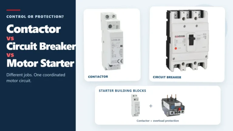
Figure 1. Contactors, circuit breakers, and motor starters solve different control and protection tasks. These three devices often appear in the same motor-control panel, but they solve different problems. A contactor handles frequent, remote, or automatic switching during normal operation. A circuit breaker interrupts abnormal current within its rated capability. A motor starter normally combines […]
Introduction The concept of remote tripping is simple, but in actual operation, project teams often encounter difficulties in specifying the components. The panel factory may require circuit breakers triggered by fire alarm relays, PLC outputs, building management system instructions, or other coordinated control. At this point, “diversion tripping” is only the first step in the […]
The main types of circuit breakers used in low-voltage distribution include miniature circuit breakers (MCBs), molded case circuit breakers (MCCBs) and residual-current devices such as RCCBs and RCBOs. They are not interchangeable. MCBs and MCCBs are selected for overcurrent protection in different circuit roles, an RCCB provides residual-current protection without integral overcurrent protection, and an […]