How Do You Test an MCCB? Methods, Standards, and What Each Test Tells You
Published: Author: Conor
You test an MCCB by measuring insulation, contact resistance, and trip operation using the right method for your symptoms, risk level, and outage constraints.
If your breaker is tripping unexpectedly, running hot, or simply aging without any test history, guessing is expensive. Testing a molded case circuit breaker isn’t something you do by flipping a handle and hoping for the best. It requires specific measurements, proper equipment, and knowing what each result actually tells you.
In this guide, we break down the common molded case circuit breaker testing methods, what problems each one can (and can’t) confirm, and how to choose the simplest test that answers your real question—without rushing into unnecessary replacements.
What “Testing an MCCB” Means (And What It Doesn’t)
Testing an MCCB means measuring its electrical and mechanical performance against manufacturer specifications using proper test equipment.
In practice, you are checking measurable parameters like insulation resistance, contact resistance, trip characteristics, and operating time, then comparing those values to known acceptable ranges or baseline data.
What testing does not do is answer every protection question. It shows how the breaker performs under specific test conditions—not how it will behave in every real-world scenario.
Testing vs Inspecting vs Exercising: Key Differences
Inspection, exercising, and testing are three different activities, and confusing them is a common maintenance mistake.
Inspection is visual. You look for physical damage, corrosion, loose terminations, or signs of overheating, usually with nothing more than a flashlight.
Exercising is mechanical. You operate the handle, feel for smooth motion, and listen for abnormal sounds. This helps keep the mechanism free but does not verify electrical performance.
Testing is measurement-based. You use instruments to quantify insulation resistance, contact resistance, or trip behavior and confirm those values meet specifications.
Each step answers a different question. Relying on only one gives you an incomplete picture of the breaker’s condition.
What MCCB Testing Can Confirm, and What It Cannot
MCCB testing confirms how a breaker performs today under defined conditions—but it does not guarantee system-level protection or future reliability.
MCCB testing can confirm the following conditions:
Insulation condition between conductors and ground
Contact resistance and connection quality
Trip operation under specific test conditions
Operating mechanism function
Response time to overcurrent
MCCB testing cannot confirm the following:
System-level protection coordination without engineering analysis
Performance under all possible operating conditions
Future reliability (testing shows current condition only)
Whether the breaker is properly sized for your application
In practical terms, a breaker can pass every test and still be wrong for the system it’s protecting. Testing shows whether the breaker works as designed—not whether that design is appropriate for your installation.
Why You’re Testing: The 4 Common Scenarios (Choose the Right Method)
You don’t test an MCCB the same way in every situation. The right testing method depends on why you’re testing and what decision you need to make next.
In practice, MCCB testing usually falls into one of four scenarios. Each one calls for a different level of effort and a different set of tests.
Commissioning / Acceptance Testing (New Installations)
The goal of commissioning tests is to establish a clean baseline before the breaker ever goes into service. At this stage, you’re not troubleshooting a problem. You’re documenting what “good” looks like so future test results actually mean something.
Typical commissioning tests include:
Insulation Resistance Testing
Contact Resistance (Micro-Ohm) Testing
Mechanical Operation Checks
Primary Injection Testing (when required by standards or criticality)
These values become your reference. Without them, future maintenance testing turns into guesswork.
Preventive testing compares today’s measurements to your original baseline to catch degradation early. Here, you’re looking for trends—not just pass/fail results. A slow rise in contact resistance or a steady drop in insulation resistance often signals problems months before a breaker actually fails.
Common preventive maintenance tests include:
Insulation Resistance Testing
Contact Resistance Testing
Thermal Imaging Under Load
Mechanical Operation Checks
If results remain stable, you extend service life. If they drift, you intervene early—when fixes are cheaper.
Troubleshooting After Repeated Trips or Abnormal Events
Troubleshooting tests answer one question: is the breaker the problem, or is it reacting correctly to something else? Random trips, overheating, or nuisance shutdowns often trigger unnecessary breaker replacements. Before you pull hardware, testing should confirm whether the trip characteristics match the actual conditions.
Testing in this scenario is symptom-driven and may include:
In many cases, testing shows the breaker is doing its job—and the real issue lies in overloads, harmonics, or system coordination.
Post-Repair / Post-Modification Verification
Any time you repair, replace components, or adjust settings, you must verify the breaker before returning it to service. This step confirms that corrective work actually solved the problem and didn’t introduce a new one.
Verification testing often includes:
Mechanical Operation Checks
Insulation Resistance Testing
Contact Resistance Testing
Functional or Injection Testing (as appropriate)
Skipping this step means energizing equipment without proof that it will operate as intended under fault conditions.
Quick MCCB Test Selection Summary (At a Glance)
Use this table to quickly match your situation with the right MCCB testing approach—without overtesting or missing critical checks.
Testing Scenario
Primary Goal
Must-Have Tests
Optional / Conditional Tests
De-Energization Required
Commissioning / Acceptance (New Installation)
Establish baseline and confirm correct installation
Visual inspection and mechanical checks verify whether the breaker is physically intact and mechanically operable—before you touch any test equipment. This is always the starting point. It costs nothing, takes minutes, and routinely eliminates obvious issues that no electrical test can fix.
During visual inspection, look for:
Physical Damage Or Cracked Housings
Loose Mounting Or Terminations
Corrosion On Terminals Or Hardware
Discoloration Or Burn Marks From Overheating
Arc Damage Or Foreign Material
Mechanical operation checks involve manually operating the handle through its full range. You’re verifying smooth motion, correct position indication, and listening for grinding, binding, or abnormal sounds.
In practice, these basic checks identify roughly 30% of suspected MCCB problems before any electrical testing is needed.
Insulation resistance testing evaluates the condition of the breaker’s internal insulation by measuring leakage current under a controlled DC voltage.
In most MCCB applications, a DC test voltage of 500–1000 V is applied, and the resulting resistance is measured. Higher resistance indicates healthy insulation, while lower values suggest deterioration.
Typical acceptance criteria start at 1 megohm or higher, though manufacturer guidance and system voltage should always take precedence.
IR testing is effective at identifying:
Moisture Intrusion
Insulation Breakdown Or Cracking
Contamination From Dust Or Chemicals
Age-Related Degradation
This test requires the breaker to be de-energized, and any connected equipment that could be damaged by the test voltage must be isolated beforehand.
Contact resistance testing measures how efficiently current flows through closed breaker contacts, revealing hidden connection and contact problems.
During this test, a known current—typically between 10 and 100 A—is applied, and the voltage drop across the closed contacts is measured. The resulting resistance value reflects contact condition and connection quality.
As a general guideline:
Healthy contacts typically measure below 100 micro-ohms
Readings above 500 micro-ohms indicate developing or active problems
Elevated contact resistance leads directly to overheating, voltage drop, reduced fault-clearing capability, and eventually premature breaker failure.
Functional Trip Testing: Verifying the Breaker’s Trip Operation
Functional trip testing confirms that the breaker’s trip mechanism can release and open the contacts when commanded.
This test is usually performed by pressing the built-in test button (if present) or manually actuating the trip mechanism. The goal is simple: verify that the latch releases cleanly and the contacts fully open.
What this test does not verify is overcurrent protection accuracy. It proves the breaker can trip mechanically, not when it will trip under real fault conditions.
Primary Injection vs Secondary Injection: When Each Is Used
Primary and secondary injection testing both evaluate trip performance, but they answer very different questions.
Primary injection testing verifies complete breaker operation by injecting real current through the main power path. Test equipment delivers hundreds or thousands of amps, exercising the sensors, trip unit, and operating mechanism together.
This makes primary injection the most comprehensive trip test available—but also the most demanding. It requires full de-energization, specialized equipment, and significant outage time.
Secondary injection testing, by contrast, evaluates the trip unit electronics independently from the power circuit. Low-level signals are injected into the sensing inputs to verify logic, timing, and settings.
Secondary injection is faster and more practical for routine checks, but it does not confirm contact performance or current path integrity.
In practice:
Use primary injection for commissioning, major maintenance intervals, post-repair verification, or when trip behavior is in doubt
Use secondary injection for routine maintenance, quick verification, or when primary injection is impractical
Thermal Imaging: Finding Hot Spots Under Real Load
Thermal imaging identifies abnormal heating while the breaker is operating under real load conditions. Using an infrared camera, you scan the energized breaker and its terminations. Temperature differences—not color alone—reveal developing problems that static tests can miss.
As general guidance:
Around 10°C above ambient is usually normal
20–40°C above similar components warrants investigation
50°C or more above ambient requires immediate corrective action
Thermal imaging is especially effective at detecting loose connections, unbalanced loads, undersized conductors, and failing contacts. This is also the only commonly used MCCB test that is performed while the breaker remains energized.
Power Quality / Load Study Checks (When Tripping Isn’t a Breaker Problem)
Power quality and load studies help determine whether nuisance tripping is caused by the electrical system rather than the breaker itself.
In many cases, an MCCB trips correctly in response to harmonics, inrush currents, voltage sags, or distorted waveforms. Replacing the breaker without identifying these conditions simply repeats the problem.
One facility in Ohio replaced three MCCBs in an attempt to stop nuisance tripping. Testing showed the breakers were operating correctly. The real issue was harmonic current produced by variable frequency drives. Power quality monitoring revealed the cause. After installing harmonic filters and adjusting breaker sizing, the tripping stopped—without replacing any additional breakers.
How to Choose the Right MCCB Test (Decision Guide)
The right MCCB test depends on three things: what you’re seeing, what you can realistically shut down, and what happens if the breaker fails to operate.
Use the guidance below to narrow your testing to what actually matters—without skipping critical checks or overtesting out of caution.
Choose Based on Symptoms: Overheating, Nuisance Tripping, or Aging Equipment
Start by matching the test to the symptom you’re actually observing. Different symptoms point to very different failure modes.
Symptom: Overheating or Burning Smell
Begin with thermal imaging while the breaker is energized to identify abnormal temperature rise. After de-energizing, follow up with contact resistance testing to confirm whether poor connections or degraded contacts are causing the heat. Always verify that load current aligns with the breaker’s rating. (If one phase is significantly hotter than the others, contact resistance is often the root cause.)
A manufacturing plant discovered one phase operating 30°C hotter than the others. Contact resistance testing showed 800 micro-ohms on that phase compared to 60 micro-ohms on the remaining phases. Replacing the breaker eliminated the overheating.
Symptom: Nuisance Tripping Measure actual load current first. Many “breaker failures” are simply overloads or transient conditions. If load levels are normal, injection testing can verify whether trip characteristics still match the breaker’s settings and design.
Symptom: Aging Equipment With Unknown History Start with visual inspection and mechanical operation checks. If no obvious issues appear, proceed with insulation resistance and contact resistance testing to establish a baseline before deciding on further action.
Choose Based on Constraints: Outage Time, Critical Loads, and Access
Practical constraints often matter as much as technical ones. Outage time and access limitations should shape your test plan.
Limited Outage Windows (2–4 Hours) When time is tight, focus on tests that provide the most information quickly: visual inspection, mechanical operation checks, thermal imaging, insulation resistance, and contact resistance testing. Primary injection testing usually exceeds short outage windows and should be deferred unless risk demands it.
Critical Circuits That Cannot Be Interrupted For circuits that must remain energized, thermal imaging and load monitoring can be performed in service. Schedule comprehensive testing—especially injection testing—during planned outages or maintenance windows only.
One data center evaluates critical MCCBs during quarterly maintenance periods. Full primary injection testing is performed on redundant systems while alternate feeders carry the load, maintaining uptime without sacrificing verification.
Choose Based on Risk: What Happens If the Breaker Fails to Operate?
Risk determines how much certainty you need. The higher the consequence of failure, the more comprehensive your testing should be.
Life Safety Circuits These circuits demand the highest confidence. Comprehensive testing—including primary injection—is appropriate to confirm that the breaker trips when required and remains stable during normal operation.
High-Value Processes or Equipment For processes where downtime or damage is costly, full testing is justified. Insulation resistance, contact resistance, and periodic injection testing establish baselines and allow trend tracking over time.
Standard Commercial Circuits For most commercial applications, visual inspection, mechanical operation checks, insulation resistance, and contact resistance testing provide sufficient coverage at reasonable cost.
A hospital conducts annual primary injection testing on all life safety MCCBs. As a result, they have not experienced a single breaker failure during an actual emergency event.
Testing Safety and Practical Boundaries
MCCB testing exposes technicians to energized equipment, high fault currents, and elevated test voltages. Safety is not optional, and shortcuts here carry real consequences.
Who Should Perform MCCB Testing and Why Qualifications Matter
MCCB testing must be performed by qualified electrical personnel who understand both the hazards and the test equipment involved.
In this context, qualified means more than holding a license. It includes hands-on experience with the specific test instruments, an understanding of electrical hazards, the ability to interpret results correctly, and preparedness for abnormal or emergency conditions.
Primary injection testing demands particular caution. These tests intentionally introduce fault-level currents into the system. A single setup error can result in arc flash exposure, severe equipment damage, or personal injury.
Tests That Typically Require De-Energizing vs Tests That Can Be Done In-Service
Not all MCCB tests can be performed on energized equipment, and confusing this boundary is a common safety mistake.
The following tests require de-energization of the breaker and associated circuits:
Insulation resistance testing
Contact resistance testing
Primary injection testing
Secondary injection testing
Most mechanical operation checks
The following tests can typically be performed while the breaker remains in service, provided appropriate PPE and procedures are used:
Thermal imaging
Load current measurement
Visual inspection (with appropriate PPE)
Some power quality monitoring
When uncertainty exists, de-energizing the equipment is the safer choice. No diagnostic result justifies unnecessary exposure.
How to Interpret Results: What Counts as a Red Flag?
Test results only become meaningful when you compare them against limits, baselines, and operating context. A number by itself is not a diagnosis.
Common Red Flags and What They Usually Indicate
Certain test results consistently point to developing or active MCCB problems. These are the values that warrant closer attention.
Insulation Resistance Below Acceptable Limits Insulation resistance values falling below 1 megohm often indicate moisture intrusion, contamination, or insulation degradation. Readings below 0.5 megohms typically require immediate investigation, especially in higher-voltage systems.
Elevated Contact Resistance Contact resistance readings above 500 micro-ohms suggest oxidation, wear, or poor contact pressure. Values exceeding 1000 micro-ohms are strong indicators of advanced contact damage and usually justify repair or replacement.
Trip Characteristics Outside Tolerance Measured trip currents deviating more than ±20% from nameplate or expected values often point to calibration drift, sensor issues, or electronic trip unit failure.
Abnormal Temperature Differences Between Phases Temperature differences exceeding 15°C between phases commonly indicate loose connections, unbalanced loading, or a deteriorating contact on the hotter phase.
Excessive Mechanical Resistance Handles that require unusual force or feel inconsistent during operation may signal internal corrosion, mechanical wear, or damaged components.
Red Flags Don’t Always Mean Immediate Replacement
Not every red flag demands immediate replacement, but some leave little room for delay. Context matters.
At a chemical plant in Texas, contact resistance testing revealed 1200 micro-ohms on a main distribution breaker. Visual inspection confirmed severe contact pitting, and the breaker had been in service for 18 years. Replacement was the correct decision.
Two months later, a neighboring breaker on the same bus failed catastrophically during a fault. Post-event testing showed that breaker also had elevated contact resistance—but it had not been tested or addressed earlier.
This illustrates the real risk: red flags do not act in isolation, and ignoring them on similar equipment can have serious consequences.
What to Do After a Failed or Marginal Result
Retesting vs. In-Depth Testing vs. Repair or Replacement
Choose the next action based on confidence in the result and the severity of deviation.
Retest First (Confirm the Measurement) Retesting is appropriate when results are unexpected, borderline, or inconsistent with operating history. Before escalating, verify test setup, connections, and procedures. If possible, repeat the test with different equipment or have a second technician perform the measurement.
Retesting often eliminates false failures caused by poor connections, instrument drift, or procedural error.
Escalate to In-Depth Testing (Find the Root Cause) When retesting confirms abnormal results but the breaker has not clearly failed, deeper testing is the right next step. Additional diagnostics should clarify whether the issue is localized—such as a single degraded contact—or systemic, such as insulation breakdown or trip unit drift.
At this stage, the goal is understanding, not replacement.
Repair or Replace (When Limits Are Clearly Exceeded) Repair or replacement is justified when results fall well outside acceptable limits, when multiple indicators point to the same failure mode, or when the breaker’s age and service conditions leave little margin for continued operation.
This decision should be based on confirmed data, not a single borderline reading.
How to avoid unnecessary replacement
The most common misjudgment is treating “below baseline” as “failed.”
Baseline values are reference points, not automatic pass/fail thresholds. A moderate deviation may indicate early wear rather than imminent failure, especially on newer equipment or lightly loaded circuits.
To avoid unnecessary replacement:
Compare results against manufacturer limits, not just historical baselines
Evaluate trend direction (stable vs. rapidly degrading)
Factor in breaker age, duty cycle, and operating environment
For example, an 8-year-old breaker with slightly elevated contact resistance may remain serviceable with increased monitoring. A 20-year-old breaker showing the same readings carries significantly higher risk and often warrants replacement.
Sound decisions balance measured data with context. Replacing equipment too early wastes capital. Replacing it too late risks unplanned outages or damage.
Recommended Testing Frequency and Documentation (Maintenance Program)
MCCB testing frequency should be driven by risk, not habit. Criticality, operating conditions, and failure consequences matter more than fixed calendar intervals.
Risk-Based Testing Intervals: What Drives Frequency
Testing intervals should increase as the consequences of failure increase. A risk-based approach avoids both overtesting and dangerous neglect.
Critical Circuits Circuits supporting life safety systems, essential services, or regulatory requirements warrant the highest level of confidence. Annual comprehensive testing—including primary injection—is often justified to verify both trip performance and mechanical integrity.
Important Circuits For circuits feeding high-value processes or equipment, annual basic testing is typically sufficient. This usually includes insulation resistance, contact resistance, and mechanical operation checks. Primary injection testing can be performed on a longer cycle, often every 3–5 years, depending on operating history and environment.
Standard Commercial Circuits Most standard commercial circuits do not require frequent comprehensive testing. Basic testing every 3 years is often adequate, with primary injection performed every 5–10 years, or omitted entirely when risk is low and historical performance is stable.
Why Baselines and Trend Tracking Matter More Than Single Results
One test result is a snapshot. Trends tell the real story.
Baseline measurements taken during commissioning or early service establish what “normal” looks like for a specific breaker in a specific environment. Without that reference, future test results lack context.
Trend tracking allows you to detect:
Gradual insulation degradation
Increasing contact resistance
Slowly changing trip behavior
These changes often develop long before a breaker fails. Facilities that track trends typically replace breakers before failure, not after an outage or incident. For a deeper look at how testing fits into a long-term program, see our guide onMCCB maintenance and risk-based breaker upkeep.
Test Report Checklist: What to Document and Why It Matters
Test documentation is not paperwork—it’s the memory of your electrical system.
Every MCCB test should generate a report that includes:
Test Conditions (date, ambient temperature, technician, equipment used)
Tests Performed (methods and procedures)
Measured Results (actual values, not just pass/fail)
Evaluation (pass, marginal, or failed)
Corrective Actions (if required)
Next Scheduled Test Date
Good documentation serves three purposes: it proves due diligence, supports trend analysis, and protects the facility legally after incidents or audits. Test reports should be retained permanently. Historical data often becomes more valuable than the most recent test.
Common Mistakes in MCCB Testing (And How to Avoid Them)
Most MCCB testing failures don’t come from bad instruments—they come from bad assumptions. Learning from common mistakes is cheaper than learning from incidents.
Mistake 1: Confusing “Pass” With “Proven for All Conditions”
Passing a test does not mean the breaker is proven for every operating condition.
All MCCB tests are performed under defined conditions. A breaker that passes primary injection testing at 25°C may behave differently when operating continuously at 45°C, under harmonic distortion, or near its thermal limits.
Testing confirms that a breaker meets specifications under test conditions. It does not eliminate the need to consider real-world loading, ambient temperature, and system behavior.
How to avoid this mistake
Use test results as validation—not as a blanket guarantee. Always interpret results alongside operating conditions.
Mistake 2: Testing the Breaker but Ignoring the System
An MCCB does not operate alone—it operates as part of a coordinated protection system.
Perfectly functional breakers are often replaced because of nuisance tripping caused by upstream coordination issues, incorrect sizing, or system changes that were never accounted for.
In many cases, the breaker is reacting correctly to conditions the system is creating.
How to avoid this mistake Verify coordination, load characteristics, and upstream/downstream settings before condemning the breaker. Fixing the system often solves the problem without replacing hardware.
Mistake 3: Jumping Straight to Complex Tests and Skipping the Basics
Skipping basic checks is one of the fastest ways to waste time and money.
Visual inspection and mechanical operation checks routinely identify loose terminations, physical damage, incorrect settings, or obvious overload conditions. Roughly 30% of suspected MCCB problems are found at this stage.
Advanced testing cannot compensate for missed basics.
How to avoid this mistake Always start with visual and mechanical checks. Escalate only when simple explanations have been ruled out.
Closing Thoughts
MCCB testing isn’t mysterious. It’s disciplined measurement, interpretation, and decision-making.
The most effective testing programs choose tests based on symptoms, constraints, and risk. They start simple, escalate only when needed, interpret results in context, and document everything to support long-term decisions.
The goal isn’t perfect testing. It’s appropriate testing—testing that balances cost, exposure, and real operating conditions. Facilities that follow this approach spend less on unnecessary replacements, catch problems earlier, and maintain more reliable electrical systems over time.
Testing gathers information. What you do with that information determines whether your MCCBs remain assets—or become liabilities.
If you need support building a risk-based MCCB testing or maintenance program, the team at Oohmage can help assess your current setup and define a testing strategy that fits your equipment, uptime requirements, and compliance needs.
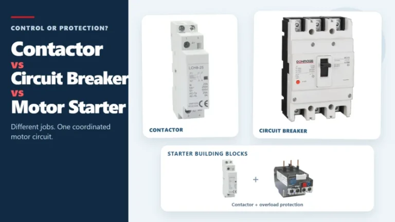
Figure 1. Contactors, circuit breakers, and motor starters solve different control and protection tasks. These three devices often appear in the same motor-control panel, but they solve different problems. A contactor handles frequent, remote, or automatic switching during normal operation. A circuit breaker interrupts abnormal current within its rated capability. A motor starter normally combines […]
Introduction The concept of remote tripping is simple, but in actual operation, project teams often encounter difficulties in specifying the components. The panel factory may require circuit breakers triggered by fire alarm relays, PLC outputs, building management system instructions, or other coordinated control. At this point, “diversion tripping” is only the first step in the […]
The main types of circuit breakers used in low-voltage distribution include miniature circuit breakers (MCBs), molded case circuit breakers (MCCBs) and residual-current devices such as RCCBs and RCBOs. They are not interchangeable. MCBs and MCCBs are selected for overcurrent protection in different circuit roles, an RCCB provides residual-current protection without integral overcurrent protection, and an […]