Quick answer: A fuse symbol identifies an overcurrent protective device connected in series with a circuit. Its exact graphical form can vary by drawing standard and convention, so confirm the drawing legend and applicable standard before identifying or specifying the device.
We’ve talked about electrical symbols. Now let’s learn about fuse electrical symbols! Fuse electrical symbols are standardized graphic symbols that show different kinds of fuses and associated protective devices in electric schematics. They are crucial in the design, troubleshooting, and maintenance of electrical systems.
What Are Fuse Electrical Symbols?
The fuse electrical symbols are representations of physical fuses that can protect circuits against overcurrent conditions. Be it a generic fuse or a fast-blow fuse acting in a short time to spikes, the symbol gives a shorthand method to discern the protection in the system.
Precise interpretation of these symbols is vital to ensure electrical installations work correctly and safely. Misinterpretation can lead to improper maintenance, faulty repairs, and even hazardous conditions. Mastering fuse electrical symbols will allow professionals to avoid equipment damage and reduce the possibility of electrical fires or malfunctions.
This is a generic symbol for a fuse that is on many schematic drawings. It is used to indicate a device that would melt its internal element when current flows above safe levels. This is universally regarded as the protection against overcurrent provided by fuses.
Note: Fuse symbols may vary between drawing standards and company conventions. Use the drawing legend and the applicable standard; this page’s illustrations are explanatory examples, not certified reproductions of a specific standard.
Thermal Fuse Symbol: Protection against Overheating
Thermal fuses respond to temperature at the device, not directly to circuit current. They are commonly used in appliances and equipment where excessive heat must permanently open the circuit. The symbol indicates a temperature-sensitive protective device; its rated operating temperature and electrical limits must be confirmed from the selected device’s data sheet.
Fast Blow Fuse Symbol: Instantaneous Protection
Fast-acting fuses are designed to clear qualifying overcurrents faster than time-delay fuses, but they do not operate at one universal instant. Clearing time depends on the fuse series, overcurrent magnitude, time-current curve and application conditions. Use the selected fuse’s data sheet to verify protection for sensitive electronic components.
Unlike fast blow fuses, slow blow fuses can withstand momentary surges of high current. This property makes them particularly suitable for those applications where surges of temporary current are found, such as in motor startups.
Special Fuse Symbols for Advanced Protection
Fuse Switch Symbol: Integrated Protection and Control
A fuse switch incorporates both a fuse and a switch into one, therefore allowing circuit interruption while at the same time providing for manual control. The fuse switch symbol would be designed to indicate that it is able to serve dual purposes for protection against overcurrent and to manually disconnect a circuit when necessary.
Fuse with Alarm Contact Symbol: Integrated Notification Systems
Some of the fuses have an alarm contact integrated to indicate that the fuse has blown. This kind of fuse is very useful where early detection of fault in the system becomes crucial. Such a fuse, having an alarm contact, uses an additional pointer to indicate dual functionality—both protection and indication.
Oil Type Fuse Symbol: Enhanced Safety in High-Current Applications
Oil type fuses are used for high-current applications such as in power distribution systems. The oil within the fuse has a cooling effect to enable the extension of breaking capacity. Their symbols commonly contain components to denote the oil environment.
Striker Fuse Symbol: Visual Fuse Status Indicator
Striker fuses incorporate a striker pin that serves as an indication of the fuse condition. When the fuse blows, the striker is freed, giving an instant visual indication.
Fuse Switch Disconnector Symbol: A Dual Function Fuse
The fuse switch disconnector is a peculiar device that combines a fuse with a disconnector switch. This dual functionality allows the device not only to protect against overcurrent but also to completely isolate a circuit for maintenance or in an emergency state.
Fuse switch disconnectors have many industrial and utility applications where safe circuit disconnection is needed without interrupting the operations of an overall system. For this reason, they have become indispensable components of modern electrical safety systems.
Beyond Fuses: Related Symbols in Circuit Protection
Though fuses are central in circuit protection, other devices play critical roles in the protection of electrical systems. Their symbols will be understood along with those of fuse symbols for completeness in circuit design.
Circuit breakers are automatic switches that protect against short circuits and heavy loads. Their symbols range from single-pole to three-pole representation explaining the function of control and interrupting the flow of current without having them replaced upon their operation.
Fuse symbols are used to depict the protective elements within the circuit panels and distribution boards. These are to be used upon examination of a circuit diagram so that the homeowners or the electricians may promptly know what protection has been afforded for overcurrent in each circuit.
Fuse Symbols in Industrial and Commercial Settings
Electrical safety is the most crucial feature in industrial and commercial settings. Hence, heavy-duty fuse symbols are quite common in situations where high currents and complex circuits are the norm. Proper interpretation of these will ensure that the maintenance teams will easily identify the issues and will take quick action with minimal downtime, enhancing the safety features.
The Role of Fuse Symbols in Automotive and Transportation Circuits
Fuse symbols also refer to the protection of various sub-systems in automotive electrical systems. Mastery of such symbols by technicians helps them troubleshoot problems quickly and proficiently for reliable performance of the vehicle.
Best Practices for Using Fuse Electrical Symbols
Proper interpretation of the fuse electrical symbols is vital for both design and troubleshooting.
First, identify the fuse type and base fuse symbol from fuse manufacturers. Then identify the additional indications of either alarm contacts or the type of oil used that modifies the function of the fuse.
Study standards set by IEC, IEEE, and ANSI to help explain the usage and meaning of a symbol.
Some similar signs will bring about confusion, like fast blow and slow blow fuses. Clarifying the differences between similar electrical symbols can make your work easier.
By using the above practices, engineers and technicians can have accurate interpretations of the fuse symbols that will keep the electrical system more reliable and safer.
Final Thoughts on Improving Electrical Safety
From generic fuses to more specialized devices like fuse switch disconnectors and surge protectors, these symbols convey important information on how the circuit is protected from overcurrent, overheating, and voltage surges.
In-depth knowledge of fuse electrical symbols allows professionals to undertake designs, maintenance, and troubleshooting of electrical systems with confidence. Integrating these symbols into your workflow and keeping yourself updated about the latest standards will go a long way in improving the safety and reliability of your electrical installations.
Additional learning on circuit protection can be done by studying resources on it, attending workshops on electrical safety, and checking updated standards by IEC, IEEE, and ANSI.
To learn about other electrical symbols, read related articles:
OOHMAGE manufactures and supplies low-voltage circuit protection and power distribution products for AC and DC applications. When a schematic identifies a fuse but the required model is unclear, confirm the circuit voltage, rated current, time-current characteristic, breaking capacity, installation method and applicable documentation before selection.
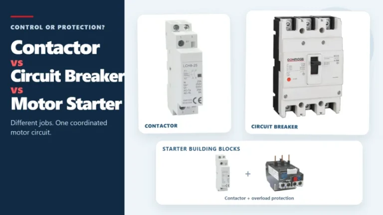
Figure 1. Contactors, circuit breakers, and motor starters solve different control and protection tasks. These three devices often appear in the same motor-control panel, but they solve different problems. A contactor handles frequent, remote, or automatic switching during normal operation. A circuit breaker interrupts abnormal current within its rated capability. A motor starter normally combines […]
The main types of circuit breakers used in low-voltage distribution include miniature circuit breakers (MCBs), molded case circuit breakers (MCCBs) and residual-current devices such as RCCBs and RCBOs. They are not interchangeable. MCBs and MCCBs are selected for overcurrent protection in different circuit roles, an RCCB provides residual-current protection without integral overcurrent protection, and an […]
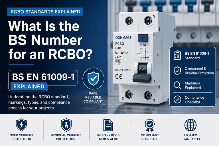
Introduction If you are searching for the RCBO BS number, the answer most commonly required in UK and IEC-based electrical procurement is BS EN 61009-1. This is the principal product standard associated with residual current circuit breakers with overcurrent protection used in residential, commercial, and similar installations. However, merely the BS number is not sufficient […]