Understanding Electrical Symbols: A Complete Guide
Published: Author: Conor
All kinds of electrical symbols are applied as representatives of general vocabulary in schematic circuits. This would enable engineers and other electricians to easily design the circuits and simplify work through understanding.
Reducing such cumbersome physical parts to simple, standard images would greatly help to make sure how to do a particular job is communicated much faster across various geographical and linguistic lines. Keep reading this guide to understand electrical symbols.
Electrical symbols are graphic representations of electrical components, systems, and interconnections of such components in circuit diagrams. It gives a graphical expression for illustrating the function or operation of an electrical system in an abstract form. Through this use of standardized symbols, the circuit designer is capable of conveying voluminous information concerning a circuit without extensive written descriptions.
For instance, the resistor symbol represents how electrical resistance is added to the circuit, while the capacitor symbol represents how electrical charge is stored. Using electrical symbols simplifies complex circuits into more comprehensible forms for debugging.
Electrical Symbols: The History
Since the founding of electrical engineering, electrical symbols have been developed. Before standardized symbols existed, circuit diagrams were either highly complicated or incoherent. Thus, there was much confusion in the designing and analyzing process. As more electrical systems became evident, so did engineering practices for unification.
It wasn’t until the late 19th and early 20th centuries that standardization began to take place, driven by organizations such as the International Electrotechnical Commission (IEC), the Institute of Electrical and Electronics Engineers (IEEE), and the American National Standards Institute (ANSI). These set standards unified the graphical representation of components, ensuring that circuit diagrams were universally understood.
Why Electrical Symbols Matter
Electrical symbols can represent intricate electrical designs in a simplified, concise way. These symbols are universal. Engineers and technicians from any part of the world can easily understand the diagram without any language problems.
At the same time, they simplify the visual complexity of the circuits, reducing what would otherwise be a mess if there were actual pictures of components used. Also, knowledge of electrical symbols will enable engineers to quickly trace faulted components and perform effective repairs.
Key Electrical Symbols in Circuit Diagrams
Electrical diagrams for AC and DC circuits depend on the same basic set of symbols that represent components.
Basic Components: Resistors, Capacitors, and Batteries
Resistor Symbol: The resistor is represented by a zigzag line showing the resistance it creates to the current flow. Further, this may be slightly different for various resistors.
Capacitor Symbol: A capacitor is an electrical component for storing energy. It is represented by two parallel lines usually separated by a gap.
Battery Symbol: The general representation of batteries consists of two parallel lines, one longer than the other, where the longer line shows the positive terminal and the shorter line shows the negative terminal.
Switches and Conductors
Switch Symbol: A switch (pushbutton switch, isolator switch, etc.) is represented as a break in the line, at which a small circle or lever may exist. The variation depends upon whether the switch is single-pole, double-pole, etc.
Conductor Symbol: Conductors or wires are usually represented by straight lines that connect the various components. They illustrate the route that electrical current will take.
Ground and Earth Symbols
Ground Symbol: The ground symbol is essentially an inverted triangle with three horizontal lines set beneath it. This symbolizes the earth connection that will keep the system grounded, thus safe and stable.
Earth Symbol: Similar to the ground symbol, the earth symbol denotes a physical connection to the earth usually for electrical safety.
AC and DC Electrical Symbols
The symbols for both AC and DC are similar. Both AC and DC electrical symbols are used to show resistors, capacitors, and switches but are applied differently because of the fundamental differences in AC and DC power systems.
AC Circuit Symbols
In AC circuits, some symbols are specific to components for handling alternating current.
AC Power Symbol: This symbol shows an alternating power supply that changes in direction and magnitude.
Transformer Symbol: The transformer is represented by a set of two inductive coils and is often connected by a line. This is the symbol to represent the step-up or step-down voltage functionality of transformers.
Inductor Symbol: Inductors are components that store electrical energy in magnetic fields. The inductor symbol consists of a set of loops or coils.
DC Circuit Symbols
DC Power Symbol: The DC power source symbol includes a battery or voltage source and a straight line to show the constant flow of current in one direction.
Diode Symbol: The diode symbol is applied in DC for the purpose of controlling the direction of flow in DC circuits. In DC systems, diodes are essential in allowing the flow of current in one direction. This is expressed by the use of a triangle pointing towards a line.
Grounding Symbols: Grounding is crucial for safety in electrical systems. The ground symbol is used to show that certain components are connected to the earth for safety reasons.
Fuse and Circuit Breaker Symbols: The general symbol for a fuse is essentially a rectangle or a square with a line through it, showing it to blow under too much current passage. The circuit breaker (miniature circuit breaker, DC circuit breaker, etc.) generally possesses a similar symbol but has some switch-like features to mean it could be reset after the trips.
Relay and Contact Symbols: Relays are represented by a rectangle with a coil inside. These symbols indicate the use of relays for controlling circuits remotely or automatically.
Capacitor with Diode Symbol: This combined symbol is used in applications like rectification, where capacitors and diodes work together to convert AC to DC.
Conclusion
Electrical symbols are the language of the electrical and electronic engineering world. They give a simplified and unified way to represent complex circuits and components that allow professionals to design, analyze, and troubleshoot electrical systems more easily. From AC to DC, understanding the different electrical symbols is crucial to effectively communicate electrical design for the safety and functionality of the system.
These are fundamental symbols in the aspect of electronics in circuit designs and analysis as electrical technology keeps on unfolding to make the work much easier and more efficient globally.
FAQ
What is the purpose of electrical symbols in circuit diagrams?
Electrical symbols show different electrical components in circuit diagrams and their functions. They ensure a standardized way of visually communicating the design, operation, and connections of the entire circuit so that other engineers and technicians understand and troubleshoot electrical systems with ease. Electrical symbols simplify complex components into easily recognizable symbols, which enhance clarity and, ultimately, efficiency in circuit design.
How are electrical symbols standardized?
Electrical symbols have been standardized by organizations like the International Electrotechnical Commission (IEC), the Institute of Electrical and Electronics Engineers (IEEE), and the American National Standards Institute (ANSI).
These organizations have developed common sets of symbols that are followed around the world. It means standardization will keep electrical diagrams universally understood, whichever the place or the language.
Why is it necessary to understand electrical symbols for circuit troubleshooting?
Electrical symbols are important in the diagnosis of problems in a circuit. From an accurate diagram, a technician or engineer can identify which component is malfunctioning, such as a resistor that has been broken or a faulty switch. Knowing what the symbols mean allows the professional to identify where the problem is and thus make quicker repairs or adjustments.
Are electrical symbols the same worldwide?
Yes, most electrical symbols are standardized worldwide, which means that circuit diagrams can be read by professionals regardless of their location.
Although there might be minor regional variations because of local preferences or standards, international organizations have developed comprehensive sets of symbols recognized globally, which enables communication across the globe in this particular field of engineering.
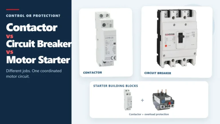
Figure 1. Contactors, circuit breakers, and motor starters solve different control and protection tasks. These three devices often appear in the same motor-control panel, but they solve different problems. A contactor handles frequent, remote, or automatic switching during normal operation. A circuit breaker interrupts abnormal current within its rated capability. A motor starter normally combines […]
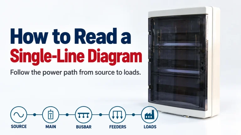
A single-line diagram can look simple and still be difficult to read. One line may represent a multiphase circuit, a small symbol may stand for a major protective device, and a short label may carry the information that determines what equipment belongs downstream. The most reliable way to read a single-line diagram is to follow […]
Figure 1. Three-phase SPD selection starts with system facts, not the largest kA number. A three-phase surge protector should not be selected by the largest kA number on its label. First confirm the system voltage, whether a neutral is present, the earthing arrangement, the installation point, and the required SPD type. Then compare Uc, Up, […]