MCCB Selection Guide: How to Choose Trip Units, Frame Size, and Interrupt Rating
Published: Author: Conor
Choosing the right molded case circuit breaker (MCCB) means matching the breaker’s protection characteristics to your system’s voltage, load profile, and available fault current — not just picking a rated current value.
An undersized breaker risks nuisance trips and overheating. An oversized one may fail to protect cables during a fault. The right selection balances:
Continuous Load Current
Frame Size
Trip Unit Type
Interrupt Rating
Panel SCCR And Applicable Standards
In this guide, we’ll walk through a practical, step-by-step MCCB selection process, explain how engineers coordinate protection, and highlight common mistakes that lead to failure in real installations.
A Step-by-Step MCCB Selection Process
Selecting an MCCB follows a logical engineering sequence. Skipping steps often leads to coordination problems or under-rated protection.
Step 1: Confirm System Voltage and Application Type
Start by identifying system voltage (240V, 415V, 480V, 600V, etc.) and application type.
Voltage class determines:
Insulation Rating
Interrupt Capacity
Standard Compliance (UL 489 or IEC 60947-2)
For example, a 480V motor control center requires a different breaker class than a 240V distribution panel.
Application matters too:
Motor Feeders
Generator Outputs
Main Distribution Circuits
Transformer Secondaries
Motor circuits require different trip characteristics than lighting or resistive loads.
Step 2: Calculate Continuous Load Current
Determine the continuous load current using nameplate data or calculated demand.
Under NEC guidelines, breakers serving continuous loads are typically sized at 125% of continuous current.
Example
If a load draws 80A continuously:
80A × 1.25 = 100A minimum breaker rating
Ignoring this factor leads to nuisance tripping under sustained load.
Step 3: Select the Correct Frame Size
Frame size defines the maximum current capacity of the breaker housing.
Common industrial frame sizes include:
100A Frame
250A Frame
400A Frame
800A Frame
Multiple rated currents may exist within one frame size.
For example:
A 250A frame may support 100A, 150A, 200A, or 250A trip units.
Selecting a frame too close to operating limits reduces flexibility and thermal margin. Oversizing unnecessarily increases cost and may reduce coordination accuracy.
Step 4: Choose the Appropriate Trip Unit Type
Trip unit selection determines how precisely the breaker responds to overloads and short circuits.
Options typically include:
Thermal-Magnetic
Electronic
Thermal-magnetic units are suitable for simple distribution systems.
Electronic trip units provide:
Adjustable Long-Time Pickup
Adjustable Short-Time Delay
Adjustable Instantaneous Settings
Optional Ground-Fault Protection
In facilities with variable frequency drives, large motors, or selective coordination requirements, electronic units offer better control.
Step 5: Verify Interrupt Rating Against Available Fault Current
Interrupt rating must exceed the maximum available fault current at the installation point.
Typical industrial fault levels:
18kA
25kA
35kA
50kA
65kA
If the system short-circuit study shows 42kA available fault current, a 35kA breaker is unsafe — even if the load current is low.
Step 6: Confirm Panel SCCR and Code Compliance
The breaker’s interrupt rating must align with the panel’s Short Circuit Current Rating (SCCR).
Under UL systems, the lowest rated component in the assembly limits the panel SCCR.
A 65kA MCCB installed in a 22kA-rated panel does not increase the panel rating.
Always verify:
Panel Nameplate SCCR
Applicable Standard (UL 489 or IEC 60947-2)
Coordination Requirements
Understanding MCCB Frame Size vs Rated Current
Frame size and rated current are related — but they are not the same.
Frame size defines the physical and thermal limits of the breaker housing. Rated current depends on the installed trip unit inside that frame.
For example, a 250A frame can be configured with 125A, 160A, 200A, or 250A trip settings. The housing stays the same. The protection value changes.
Frame size affects:
Mechanical strength
Heat dissipation
Interrupt rating range
It does not automatically represent operating current.
Frame size affects mechanical strength, heat dissipation, and the maximum interrupt rating range. It does not automatically represent the operating current of the circuit.
Choosing a frame that is too small reduces thermal margin and may shorten breaker lifespan. Choosing one that is too large increases cost and may complicate protection coordination.
The correct frame size should align with calculated load current, available fault level, and future expansion plans.
Thermal-Magnetic vs Electronic Trip Units: How to Choose
Trip unit selection determines how accurately an MCCB responds to overloads and fault conditions. In many projects, this choice has a greater impact on system reliability than frame size alone.
When Thermal-Magnetic Trip Units Are Still Appropriate
Thermal-magnetic trip units rely on bimetal elements for overload protection and magnetic mechanisms for instantaneous short-circuit response.
They are suitable for:
Stable distribution systems
Lighting circuits
Simple commercial panels
Installations with predictable load profiles
These units are cost-effective and reliable in environments where load behavior does not vary significantly.
However, their pickup settings are fixed or minimally adjustable. They are also influenced by ambient temperature, which can slightly shift thermal response under extreme conditions.
For straightforward systems without selective coordination requirements, thermal-magnetic units remain a practical solution.
When Electronic Trip Units Become Necessary
Electronic trip units use current sensors and microprocessor-based control to provide adjustable protection settings.
They allow engineers to configure:
Long-time pickup
Short-time delay
Instantaneous threshold
Optional ground-fault protection
In systems with motors, variable frequency drives, generators, or high fault levels, electronic trip units improve coordination and reduce nuisance tripping.
For example, in a manufacturing plant with multiple motor feeders, startup inrush currents may reach six to eight times full-load current. A fixed instantaneous setting may trip unnecessarily. An electronic trip unit allows adjustment of delay and pickup thresholds to maintain protection without interrupting normal operation.
In projects requiring selective coordination or high uptime reliability, electronic trip units are often not optional — they are required by design.
Adjustable Trip Settings: Flexibility With Engineering Discipline
Adjustable trip settings give engineers more control over protection behavior — but flexibility only works when it’s supported by proper system analysis.
Without coordination studies, adjustable settings can create more problems than fixed ones.
What Adjustable Trip Units Actually Allow You to Control
Modern electronic trip units allow configuration of several key protection parameters.
Long-time pickup determines the overload threshold. Short-time delay creates a coordination window between upstream and downstream devices. Instantaneous trip defines the response to high-magnitude short circuits. Ground-fault pickup adds protection against low-level leakage currents.
These settings allow protection to match real system behavior rather than relying on fixed factory curves.
In motor circuits, for example, instantaneous pickup must exceed locked-rotor current. Otherwise, normal startup may trip the breaker unnecessarily.
Common Mistakes When Setting Adjustable Trip Units
The most common mistake is setting instantaneous pickup too low in an attempt to “protect equipment.” This often results in nuisance tripping during inrush events.
Another issue is poor coordination. If upstream delay settings are shorter than downstream clearing times, the wrong breaker opens first — shutting down a larger portion of the system.
Adjustable does not mean arbitrary.
In one typical case, a plant experienced repeated shutdowns during motor startup. The solution was not lowering thresholds further, but reviewing time-current curves and adjusting short-time delay to maintain coordination while preserving fault protection.
Proper adjustment requires data, not guesswork.
Interrupt Rating Explained: How Much Fault Current Is Enough?
Interrupt rating defines the maximum fault current an MCCB can safely interrupt without mechanical or thermal damage.
Unlike rated current, which relates to normal operation, interrupt rating only matters during short-circuit events — but when it matters, it matters immediately.
What Interrupt Rating Protects Against
During a short circuit, fault current can rise to tens of thousands of amperes within milliseconds.
The interrupt rating ensures the breaker can:
Open under high electromagnetic forces
Extinguish the arc safely
Prevent contact damage
Maintain enclosure integrity
Typical industrial interrupt ratings include 18kA, 25kA, 35kA, 50kA, 65kA, and 100kA.
Available fault current depends on transformer size, generator contribution, and system impedance. A location close to a large utility transformer may see significantly higher fault levels than a downstream branch panel.
What Happens If Interrupt Rating Is Too Low
If available fault current exceeds the breaker’s interrupt rating, the breaker may fail to clear the fault safely.
In such cases:
Contacts can weld closed
Internal arc energy may escalate
Panel components may suffer severe damage
For example, a facility with 42kA available fault current installed a 35kA-rated breaker on a feeder. During a fault event, the breaker cleared slowly and internal damage required full panel replacement.
Interrupt rating must always exceed calculated short-circuit current at the installation point.
Fault studies are not optional in high-capacity systems — they define whether protection will function as intended.
MCCB Selection for Industrial Applications
Industrial environments place very different demands on MCCBs depending on the type of circuit involved. A breaker that performs well in a distribution panel may not behave the same way in a motor feeder or generator-backed system.
Understanding these differences prevents costly coordination failures.
MCCB Selection for Motor Circuits
Motor circuits introduce high inrush currents during startup — often six to eight times full-load current.
This affects both trip unit type and instantaneous settings.
Thermal-magnetic breakers may work in small motor applications, but in systems with multiple motors or frequent starting cycles, electronic trip units provide better control. Adjustable short-time delay helps prevent nuisance trips while still maintaining short-circuit protection.
Locked-rotor current and starting time must be considered during coordination studies. Simply selecting a breaker based on rated current is not sufficient.
MCCB Selection for Generators and Power Sources
Generator-fed systems behave differently from utility-fed systems.
Available fault current is typically lower and varies depending on generator size and impedance. Because of this, interrupt rating and pickup settings must be evaluated carefully.
In some cases, breakers selected for utility-fed panels are oversized for generator-backed systems, leading to coordination challenges.
Adjustability becomes especially important when fault contribution changes under different operating modes.
MCCB Selection for Distribution Panels
In distribution panels, selectivity and coordination take priority.
Downstream breakers should clear faults before upstream feeders operate. Achieving this requires careful review of time-current curves and short-circuit levels.
Here, frame size, interrupt rating, and trip unit coordination must work together.
Industrial systems rarely fail because of one incorrect parameter. They fail when multiple small mismatches accumulate.
Application context determines which MCCB characteristic deserves the most attention.
Panel Rating and System-Level Considerations
Selecting the correct MCCB is only part of the protection strategy. The entire panel assembly must also withstand the available fault current.
Breaker performance alone does not guarantee system safety.
MCCB Interrupt Rating vs Panel SCCR
An MCCB interrupt rating defines the maximum fault current the breaker can safely interrupt.
Panel SCCR (Short-Circuit Current Rating) defines the maximum fault current the complete assembly can withstand without structural or insulation failure.
These two values are related — but they are not automatically equal.
For example, installing a 65kA-rated MCCB inside a panel with a 35kA SCCR does not increase the panel rating to 65kA. The lowest-rated component in the assembly determines the overall SCCR.
Panel SCCR depends on:
Busbar ratings
Internal wiring
Contactors and control components
Manufacturer testing or field evaluation
Why Panel Rating Must Be Verified During MCCB Selection
Ignoring panel SCCR can invalidate protection assumptions.
In many real-world failures, the breaker operated correctly — but the panel structure could not withstand the fault energy.
Proper MCCB selection must align with:
Available fault current
Verified panel SCCR
Applicable standards (UL 508A or IEC assembly standards)
System-level verification prevents compliance issues and costly redesign. Protection must be evaluated at the assembly level, not only at the device level.
UL vs IEC MCCBs: Key Standard Differences
UL and IEC standards define how MCCBs are designed, tested, and certified. These frameworks are not interchangeable, even though the devices may appear similar in function.
Understanding the difference is essential for compliance in international projects.
Different Design Philosophies Under UL 489 and IEC 60947-2
UL-listed breakers are evaluated as standalone protective devices.
IEC 60947-2, widely used in Europe and international markets, takes a system-oriented approach.
It emphasizes:
Coordination within electrical assemblies
Defined breaking capacities such as Icu and Ics
Greater engineering flexibility in protection settings
Under IEC, protection design often involves coordination studies rather than relying solely on device-level certification.
Why UL and IEC MCCBs Are Not Interchangeable
Although both standards address overload and short-circuit protection, certification assumptions differ.
A UL-listed MCCB may not satisfy IEC compliance requirements, and an IEC-certified breaker may not meet North American listing requirements under UL 489.
Using the wrong certification standard can result in inspection failure or project delays. Selection must align with the governing electrical code.
Where IEC-Certified MCCBs Are Commonly Applied
IEC MCCBs are widely used in:
Industrial facilities
Infrastructure projects
Export-oriented equipment manufacturing
Multinational industrial installations
They are particularly suitable for engineered systems where coordination and adjustable protection strategies are required.
In global projects, IEC-certified MCCBs support flexibility across varying system configurations and international standards.
NEC vs IEC: Design Philosophy Differences in Global MCCB Projects
NEC and IEC standards approach protection design differently. The difference is not about safety level, but about certification philosophy and system integration.
Aspect
NEC / UL System
IEC System
Governing Framework
NEC with UL 489 certification
IEC 60947-2
Certification Focus
Component-level testing
System-level coordination
Breaking Capacity Definition
Verified interrupt rating
Icu / Ics defined performance levels
Coordination Practice
Required in specific applications
Common in industrial design practice
Adjustability
Often predefined configurations
Broader adjustable protection ranges
In NEC-based systems, breakers are certified as individual protective devices under strict testing conditions. Compliance is primarily component-driven.
IEC systems place greater emphasis on coordination within the full installation. Engineers often design protection curves based on calculated fault levels and load behavior.
In global projects, the governing electrical code of the installation site determines which framework applies. A device certified under one system may not automatically satisfy requirements under the other.
Common Mistakes to Avoid When Selecting MCCBs
Most MCCB failures are not caused by defective devices. They result from simplified selection decisions that overlook system behavior. Several recurring mistakes appear across industrial projects.
One common error is selecting a breaker based solely on rated current. Load current is only one parameter. Fault level, coordination requirements, and future expansion must also be considered.
Another frequent issue is ignoring panel SCCR. Even if the breaker interrupt rating is sufficient, the overall panel assembly may not be rated for the available fault current. This creates compliance and safety risks.
Underestimating short-circuit current is equally problematic. Fault levels near utility transformers or large generators can be significantly higher than expected. Without a short-circuit study, interrupt rating selection becomes guesswork.
Finally, poor trip coordination can undermine an otherwise correct design. If upstream breakers trip before downstream protection clears the fault, system reliability suffers.
Effective MCCB selection requires reviewing the complete protection strategy — not just individual device specifications.
Final Thoughts
Selecting the right MCCB is not about choosing the highest current rating or the largest frame. It requires understanding load behavior, available fault levels, coordination requirements, and the governing electrical standard.
Frame size, trip unit type, interrupt rating, and panel SCCR must work together as a coordinated protection system. Proper selection should also be supported by regular MCCB maintenance, ensuring long-term performance and protection integrity throughout the equipment lifecycle.
In industrial and international projects, especially under IEC frameworks, engineering judgment plays a central role in achieving reliable and compliant protection.
If your project requires IEC-certified MCCBs designed for global applications and engineered coordination, Oohmage provides solutions built to meet international standards with long-term reliability in mind.
Electrical protection decisions affect safety, uptime, and compliance — make them with clarity and precision.
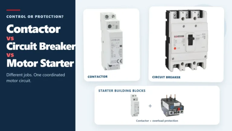
Figure 1. Contactors, circuit breakers, and motor starters solve different control and protection tasks. These three devices often appear in the same motor-control panel, but they solve different problems. A contactor handles frequent, remote, or automatic switching during normal operation. A circuit breaker interrupts abnormal current within its rated capability. A motor starter normally combines […]
A single-line diagram can look simple and still be difficult to read. One line may represent a multiphase circuit, a small symbol may stand for a major protective device, and a short label may carry the information that determines what equipment belongs downstream. The most reliable way to read a single-line diagram is to follow […]
Figure 1. Three-phase SPD selection starts with system facts, not the largest kA number. A three-phase surge protector should not be selected by the largest kA number on its label. First confirm the system voltage, whether a neutral is present, the earthing arrangement, the installation point, and the required SPD type. Then compare Uc, Up, […]