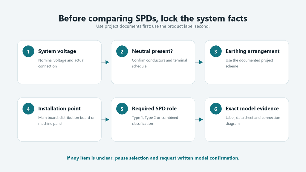
Figure 1. Three-phase SPD selection starts with system facts, not the largest kA number.
A three-phase surge protector should not be selected by the largest kA number on its label. First confirm the system voltage, whether a neutral is present, the earthing arrangement, the installation point, and the required SPD type. Then compare Uc, Up, and the applicable discharge-current ratings on the same test basis. Finally, verify the pole configuration, protection modes, backup-protection instructions, and short-circuit information in the exact model’s data sheet.
If the project information and product documents do not align clearly, pause the selection and request written model confirmation. This article is a specification-reading and quotation-preparation guide, not a wiring or installation instruction.
Quick Answer: Do Not Choose a Three-Phase SPD by Imax Alone
The label is useful, but it cannot answer every selection question. Use these seven checks in order.
Check
Why it matters
Evidence to request
1. Three-phase system
The product must be reviewed against the actual voltage, conductors, earthing arrangement, and installation point
Single-line diagram, panel specification, system voltage, and site information
2. Pole and protection configuration
Similar module counts may represent different protection modes or terminal arrangements
Full model code, connection diagram, terminal designations, and protection modes
3. SPD type
Type 1, Type 2, and combined classifications describe different test and application roles; they are not quality grades
Project requirement, risk assessment where applicable, and manufacturer classification
4. Uc
The maximum continuous operating voltage must suit the voltage applied to each protection mode
Label value plus the exact model data sheet
5. Up
The voltage protection level must be considered with equipment withstand, connection conditions, and coordination
Declared Up and the conditions under which it applies
6. In, Imax, and Iimp
All may be shown in kA, but they do not describe the same test duty
Parameter definitions, waveform labels, SPD type, and values per mode or pole
7. Backup protection and documents
The front label rarely contains the complete coordination and short-circuit information
Installation instructions, backup-device requirements, short-circuit data, and declared standards
Check 1: Start with the Three-Phase System, Not the Product Label
Figure 2. Confirm the system voltage, neutral, earthing, location, SPD role, and exact model evidence before selection.
A product label describes a device, not its electrical system. Collect the project facts before comparing products.
Project fact
Where to find it
Why the supplier needs it
Nominal system voltage and actual connection
Single-line diagram, panel schedule, or project specification
To compare the system conditions with the voltage ratings of each SPD protection mode
Phase and neutral arrangement
Diagram and terminal schedule
To determine which pole and protection configuration requires review
Earthing arrangement
Design documents prepared by qualified personnel
To assess the required protection modes and manufacturer application conditions
Installation point
Main switchboard, distribution board, machine panel, or another defined location
To relate the SPD type and coordination role to the project design
Protection objective and downstream equipment
Project specification and equipment documentation
To review the required voltage protection level and coordination
Prospective short-circuit conditions
Engineering calculation or project record
To verify the product’s declared short-circuit and backup-protection conditions
Do not assume one common three-phase voltage or earthing system applies worldwide. Even projects with the same line-to-line voltage may differ in neutral arrangement, voltage to earth, installation point, and protection design. Ask which documented SPD configuration can be reviewed against the exact system—not which product has the highest rating.
Check 2: Read the Pole and Protection Configuration Correctly
What 3P, 4P, and 3P+N labels may describe
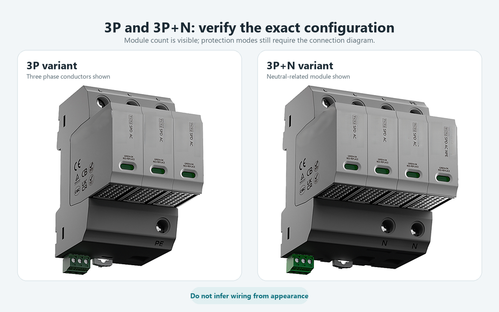
Labels such as 3P, 4P, 3P+N, or 3P+NPE do not replace a circuit description. Depending on the product, they may refer to modules, protected conductors, terminal arrangement, or protection modes.
Similar-looking devices can use different internal configurations, and enclosure width alone does not confirm suitability.
Why the neutral module is not a cosmetic difference
Where a product includes a neutral-related module or protection mode, that element forms part of the declared configuration. It should not be added, removed, or treated as interchangeable on appearance alone.
Use the exact model’s connection diagram, mode-of-protection information, and terminal designations. A qualified reviewer should compare them with the project diagram. This article provides no terminal-by-terminal wiring instructions.
Figure 3. Verified 3P and 3P+N variants; visible module count does not replace the connection diagram.
Check 3: Confirm the SPD Type and Installation Role
Type 1, Type 2, and Type 1+2 markings identify tested classifications and an SPD’s intended role. They are not a “good, better, best” scale.
Label
Buyer-level interpretation
What still needs confirmation
Type 1
The SPD has an impulse-current test classification associated with higher-energy lightning-current duty
Whether the project requires this role, the applicable Iimp value, system configuration, and coordination
Type 2
The SPD has a nominal discharge-current test classification commonly used in distribution-level surge protection
The required In and Imax values, Up, Uc, installation point, and coordination
Type 1+2
The selected product declares combined Type 1 and Type 2 test classifications
The values and protection modes declared for the exact product and how it fits the project design
The current IEC framework places common SPD requirements in IEC 61643-01:2024, AC-specific requirements in IEC 61643-11:2025, and selection principles in IEC 61643-12:2020. A standard reference alone does not establish suitability for every system or market.
Check 4: Uc—Maximum Continuous Operating Voltage
Uc is the maximum continuous operating voltage declared for an SPD or a mode of protection. In buyer terms, it answers: “What voltage can be continuously applied to this part of the SPD under its stated conditions?”
The value should be checked against the actual system voltage applied to the relevant protection mode, including the effects of the system and earthing arrangement. Do not automatically equate the nominal system voltage with Uc, and do not select the closest-looking number without understanding what conductors or terminals the value refers to.
Do: identify the voltage object—line to neutral, line to earth, line to line, or another declared mode—and compare it with the exact data sheet.
Do not: copy a Uc value from another model, another earthing arrangement, or a competitor’s selection table.
If the label shows several voltage values, record each symbol and unit exactly. A plain “385 V” is incomplete without its parameter and protection mode.
Check 5: Up—Voltage Protection Level
Up is the declared voltage protection level associated with the SPD’s limiting performance under specified test conditions. It is not the same parameter as Uc.
Uc concerns continuous voltage exposure. It helps determine whether the SPD can remain connected under the stated operating conditions.
Up concerns the voltage level associated with surge limiting. It must be considered with the impulse withstand of the equipment being protected, conductor arrangement, connection effects, and coordination with other protection stages.
A lower Up value cannot be treated as a universal guarantee of better protection. The comparison must use the same protection mode and appropriate test basis, and it must still account for installation and coordination conditions. A catalogue value alone does not promise that every downstream device will experience that exact voltage in a real installation.
Ask the supplier to state Up for the relevant mode and identify the controlling document. Send any project equipment-withstand requirement for technical review rather than requesting only “the lowest Up.”
Check 6: Compare In, Imax, and Iimp on the Correct Test Basis
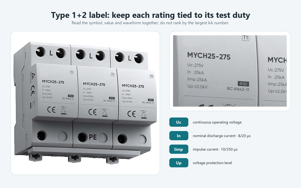
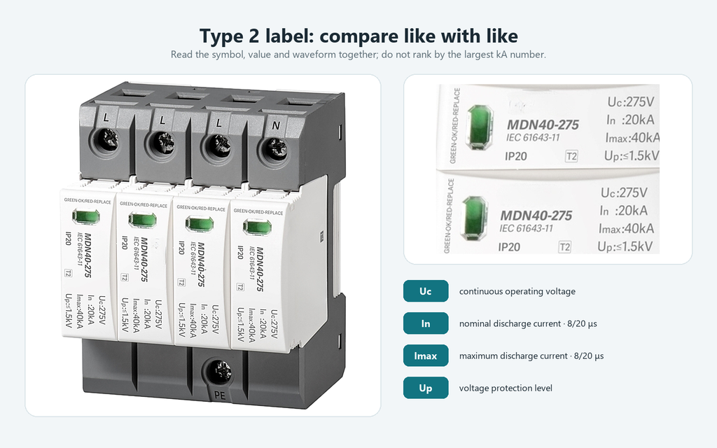
In, Imax, and Iimp can all appear as kA values, but equal units do not make them interchangeable. The waveform, SPD type, protection mode, and test definition matter.
Figure 4. Type 1+2 label: Uc, In, Iimp, and Up are separate declarations.
Parameter
Buyer question
Common IEC-style waveform label
Most closely associated with
What the number alone cannot prove
In
What nominal discharge-current duty is declared for repeated Type 2 testing?
8/20 μs
Type 2 classification and related product declarations
Service life, the number of real surges the product will survive, or complete system suitability
Imax
What maximum discharge-current value is declared under the stated Type 2 test basis?
8/20 μs
Type 2 product comparison when the same definition and conditions are used
That the largest value is automatically the best choice, or that it is equivalent to Iimp
Iimp
What impulse-current duty is declared where the Type 1 classification applies?
10/350 μs
Type 1 classification and lightning-current duty
That the product fits the project without checking Uc, Up, configuration, and coordination
Figure 5. Type 2 label: compare Uc, In, Imax, and Up on the same test basis.
Start by confirming whether each value is given per pole, per protection mode, or for a complete assembly. Then confirm that the compared products use the same parameter and test definition. Do not rank a 10/350 μs Iimp value against an 8/20 μs Imax value as if they were the same contest.
Do not convert a laboratory declaration into a lifespan promise. Real exposure and operating conditions vary. Status indicators or remote contacts on selected models also do not replace the rating review.
Check 7: Verify Backup Protection, Coordination, and Documents
The front label is the beginning of the evidence chain, not the end.
Evidence layer
What to verify
On the product label
Manufacturer, full model code, SPD type, Uc, Up, applicable discharge-current ratings, protection configuration, status marking, and referenced standard where shown
In the manufacturer data sheet and instructions
Complete rating conditions, protection modes, short-circuit information, internal or external disconnector details, maximum permitted backup protection, coordination information, dimensions, environmental limits, and document revision
In the project documents
System voltage, neutral and earthing arrangement, prospective short-circuit conditions, installation point, upstream and downstream protection, equipment withstand requirements, destination-market rules, and approval requirements
Some SPD designs contain internal disconnecting means; others require specific external backup protection under stated conditions. Never derive a universal fuse or circuit-breaker rating from another product family. Follow the instructions for the exact model and have the final coordination reviewed by qualified electrical personnel.
If a quotation lacks the current data sheet or instructions, request them before approving a substitution. Similar Type, Uc, or kA markings do not establish equivalent protection modes or backup requirements.
Once the seven checks are complete, buyers can review OOHMAGE’s AC and DC SPD product range as a commercial starting point. The category page is not a substitute for model-level documentation.
Three Outcomes After the Seven Checks
1. The system and model documents align
The stated system, ratings, configuration, and backup conditions appear consistent with the project information. Continue to technical, document, and commercial review; this is not local installation approval.
2. The label looks plausible, but documents are incomplete
The marking appears relevant, but required model documents are missing. Pause and request them; do not fill gaps from a similar model or distributor listing.
3. A system condition falls outside the declared model data
A project condition is outside the product’s stated data. A larger Imax cannot compensate; return to model selection with complete system information.
RFQ Checklist for a Three-Phase Surge Protector
A complete RFQ reduces repeated clarification.
RFQ field
Information to provide
Application
Confirm that the request is for three-phase AC; use a separate DC SPD review for a DC system
System voltage
Nominal voltage and the actual line-to-line, line-to-neutral, or voltage-to-earth information available from the project
Conductors and earthing
Whether a neutral is present and the documented earthing arrangement
Installation point
Main incoming board, downstream distribution board, machine panel, or another defined position
Required SPD role
Project-specified Type 1, Type 2, Type 1+2, or a request for technical review if not yet determined
Required ratings
Project requirements for Uc, Up, In, Imax, and Iimp where applicable, with units and test basis
Configuration
Pole count, protection modes, panel space, mounting format, and terminal constraints from the project
Coordination
Available short-circuit information, upstream protection, and any backup-protection requirement
Options
Remote status contact, replaceable modules, status indication, or monitoring requirements where needed
Data sheet, installation instructions, test or certification documents, and any approval format required by the project
For a proposed product, send the full model code and a clear label photograph. Mark unknown project values as unknown rather than estimating them.
Common Mistakes When Comparing Three-Phase SPDs
Sorting products only by Imax
Imax is one Type 2 discharge-current parameter. Correct the comparison by checking the system, Type, Uc, Up, waveform, configuration, and documents together.
Treating Uc and Up as the same voltage
Uc concerns continuous operating voltage; Up concerns declared surge-limiting performance under specified conditions. Record both and state what each value applies to.
Comparing 8/20 μs and 10/350 μs values directly
These waveforms are used for different test duties. Compare like with like and keep the parameter symbol attached to every kA value.
Inferring suitability from module count
The number of modules does not fully describe the protection modes or system fit. Use the exact connection diagram and terminal designations.
Ignoring neutral, earthing, or installation point
Those project facts can change the configuration and coordination discussion. Collect them before requesting a final model.
Borrowing specifications from another brand or series
Similar labels do not make products interchangeable. Use each manufacturer’s current document for the exact ordering code.
Ordering before the evidence is complete
A label image without a matching data sheet and installation instructions is not a complete technical package. Request the missing documents first.
Frequently Asked Questions
What does Uc mean on a surge protective device?
Uc is the maximum continuous operating voltage declared for an SPD or protection mode. It should be compared with the voltage continuously applied at the intended connection point, considering the system and earthing arrangement. It is not automatically identical to the nominal system voltage, and a universal Uc value should not be chosen without the exact product data.
What is the difference between In and Imax on an SPD?
In is the nominal discharge-current value associated with an 8/20 μs test duty. Imax is the maximum discharge-current value declared under an 8/20 μs Type 2 test basis. Compare them only within the same definitions and product conditions; neither value alone proves service life or complete project suitability.
Is a 3P SPD the same as a 3P+N SPD?
Do not assume they are the same. The labels may represent different protected conductors, modules, terminal arrangements, or protection modes. Confirm the neutral and earthing arrangement, then check the selected model’s connection diagram, protection modes, and terminal designations. This is a document review, not a wiring instruction.
Is a higher Imax always better?
No. Imax must be considered with the SPD type, waveform, In, Uc, Up, protection configuration, installation point, short-circuit conditions, and backup-protection instructions. A higher Imax cannot correct a voltage, topology, or application mismatch.
What should I send for a three-phase SPD quotation?
Send the system voltage, neutral and earthing information, installation point, required SPD type, pole and protection configuration, applicable Uc, Up and discharge-current requirements, short-circuit or backup-protection information, quantity, destination market, and required documents. Include the proposed model code and label image if available.
Final Takeaway
Start with the three-phase system, then read the label against the exact product documents. Uc, Up, In, Imax, and Iimp answer different questions, while pole labels and module counts require confirmation from the model’s connection and protection-mode information. The largest kA number cannot replace those checks.
When the system data and product documents align, move to technical and commercial review. When information is missing, request it rather than estimating. To discuss an OOHMAGE option, send the three-phase system conditions and document requirements so the available SPD series can be reviewed before quotation.
A single-line diagram can look simple and still be difficult to read. One line may represent a multiphase circuit, a small symbol may stand for a major protective device, and a short label may carry the information that determines what equipment belongs downstream. The most reliable way to read a single-line diagram is to follow […]
An AC-only miniature circuit-breaker,you cannot treat it as a DC circuit by default.Confirm before using: If the manufacturer explicitly rates the selected model for the required DC voltage, pole arrangement, polarity where applicable, fault current, and breaking capacity.Some breakers carry both AC and DC ratings, but these alone cannot reflect the actual situation. If the […]
This buyer‑focused guide compares 2‑pole and 4‑pole RCCBs for single‑phase and three‑phase‑four‑wire systems. It walks you through selecting the correct RCCB type, residual‑current sensitivity and protection coordination. Multiple practical checklists, frequent‑selection mistakes and quotation‑ready specification lists are included to help distributors, panel builders and installers specify the right residual‑current breaker and prevent unwanted tripping.