What Is an MCCB? Meaning, Ratings & Selection Guide
Published: Author: Conor
An MCCB, or molded case circuit breaker, is an overcurrent protective device used in low-voltage power distribution. It opens a circuit automatically when its trip unit detects an overload or short-circuit condition within the device’s declared operating characteristics.
Choosing an MCCB is not simply a matter of selecting an ampere value. The application must be checked against the system voltage, AC or DC configuration, load and conductor requirements, prospective short-circuit current, breaking-capacity ratings, pole arrangement, trip-unit characteristics, coordination study, installation conditions and applicable rules.
Quick answer: MCCB stands for Molded Case Circuit Breaker. It protects a circuit against specified overcurrent conditions, but its suitability depends on the exact model and installation. Before comparing an MCCB range, confirm the electrical data at the installation point rather than relying on a general current threshold.
What Is an MCCB (Molded Case Circuit Breaker)?
An MCCB is a circuit breaker enclosed in a molded insulating case. Its operating mechanism and trip unit open the contacts when current exceeds the conditions defined by the selected protection settings or fixed trip characteristics.
MCCBs are commonly used for feeders, incomers, machinery circuits and distribution equipment where the declared ratings and available protection functions suit the design. Depending on the model, the trip unit may be thermal-magnetic or electronic, and its settings may be fixed or adjustable.
The difference between an MCCB and an MCB is not that one “protects systems” while the other “protects circuits.” Both are circuit breakers used for overcurrent protection. The correct device is determined by the applicable product standard, declared voltage and current ratings, short-circuit performance, trip characteristics, installation conditions and coordination requirements.
What Is the Main Function of a Molded Case Circuit Breaker?
The main function of an MCCB is to interrupt current under specified abnormal conditions so conductors and equipment can be protected as part of a coordinated electrical design.
An MCCB may provide the following functions, depending on the model and trip unit:
Overload protection: the breaker trips according to its long-time or thermal characteristic when overcurrent persists.
Short-circuit protection: the breaker responds according to its instantaneous or short-time characteristic when fault current reaches the applicable pickup level.
Switching and isolation functions: these must be verified from the model markings, instructions and installation method. An MCCB should not be assumed suitable for isolation unless the manufacturer declares and marks that function.
Additional protection or communication functions: electronic trip units and accessories may add functions, but availability and adjustment ranges are model-specific.
A standard overcurrent-only MCCB does not replace residual-current protection where that function is required. The complete protection scheme must be selected for the earthing system, circuit purpose, local requirements and equipment being protected.
MCCB vs MCB vs RCCB: What Is the Difference?
These devices should be compared by function and declared characteristics—not by a universal current cutoff or by the value of the connected equipment.
Device
Principal function
Important boundary
MCCB
Overload and short-circuit protection according to its trip unit and ratings
Functions, settings, AC/DC suitability, breaking capacity and isolation suitability are model-specific
MCB
Overload and short-circuit protection for circuits within the device’s declared scope
Do not reject an MCB solely because of a general kA or current rule; verify the exact product standard and ratings
RCCB / RCD
Residual-current protection intended principally to reduce electric-shock hazard and, where applicable, fire risk
An RCCB does not include integral overcurrent protection; protection performance depends on the device, system and installation
RCBO
Combined residual-current and overcurrent protection
Ratings, residual-current type, tripping characteristics and application still require model-level verification
MCCB—overcurrent protection for suitable distribution and equipment circuits
An MCCB may be used on main or sub-main feeders, industrial distribution circuits, motor circuits, generator connections and other applications when its declared ratings and protection characteristics match the design.
The decision must be based on calculated load current, conductor protection, system voltage, prospective short-circuit current, trip characteristics and coordination. Equipment value or project size alone does not make an MCCB the correct choice.
MCB—overcurrent protection within its declared application
An MCB also protects against overloads and short circuits. MCBs are widely used in household, commercial and control circuits when their declared standard, voltage, current, breaking capacity and tripping characteristic are suitable.
An MCB should not be described as automatically unsuitable for motors, feeders or fault levels above an invented universal threshold. Verify the actual product ratings and the coordination study.
RCCB/RCD—residual-current protection without integral overcurrent protection
An RCCB is a type of residual-current device without integral overcurrent protection. It detects residual-current imbalance and is intended principally to provide protection against electric-shock hazard under defined conditions.
An RCCB must be coordinated with the necessary overcurrent protective device. Its residual-current rating, type, poles, voltage and application must be selected for the system and local requirements. No device should be presented as guaranteeing prevention of electric shock.
When Should You Use an MCCB?
Use an MCCB when the electrical design and the selected model’s declared characteristics make it suitable. Do not use a universal current or short-circuit threshold to choose the device family.
Check these conditions first:
System type: AC or DC, system voltage, frequency where applicable, earthing arrangement and required pole configuration.
Load and conductors: design current, load profile, conductor ampacity, installation method, ambient temperature and applicable correction factors.
Prospective short-circuit current: the calculated fault current at the installation point and the breaker’s declared breaking performance at the applicable voltage.
Trip characteristics: fixed or adjustable functions, time-current curve, motor-starting or transformer-inrush data and coordination with upstream and downstream devices.
Operational requirements: isolation marking where isolation is required, accessories, remote operation, monitoring and maintenance procedures.
Applicable rules: local electrical regulations, project specification, manufacturer instructions and qualified design review.
For motor applications, use the actual starting-current profile, starting time and time-current curves. A general multiplier cannot replace a coordination check.
industrial control panels and motor-control centres;
generator and transfer-system circuits;
commercial-building power distribution;
machinery and process equipment;
solar, battery and other DC circuits when the exact MCCB is declared for the system voltage, polarity and pole arrangement.
These are application examples, not automatic recommendations. Each circuit still requires its own load, fault-level, conductor, coordination and environmental checks.
MCCB Ratings: What Should You Check?
The nameplate and manufacturer documentation must be read together. Similar-looking breakers can have different operating voltages, breaking capacities, trip units and accessory options.
Selection field
What to verify
Why it matters
Rated operational voltage (Ue)
The declared operating voltage for the relevant AC or DC application
Breaking performance and switching duty are stated for defined voltages
Rated current and trip-unit data
Frame rating, rated current, sensor or plug rating, and the available fixed or adjustable settings
The breaker must coordinate with the load, conductors and other protective devices
Rated insulation voltage (Ui) and impulse withstand voltage (Uimp)
The separate manufacturer-declared insulation and impulse ratings
Ui should not be treated as a simple “maximum voltage”; Uimp is a different declared characteristic
Ultimate and service short-circuit breaking capacities (Icu and Ics)
Values at the applicable operational voltage and system type
A bare kA value without voltage and Icu/Ics context is incomplete
Pole arrangement and AC/DC suitability
Number of poles, polarity requirements and permitted series connection where applicable
DC interruption and pole use must follow the exact manufacturer instructions
Time-current characteristics
Long-time, short-time, instantaneous and any ground-fault functions that the trip unit actually provides
Protection and selectivity depend on the curve and settings, not just the frame size
Coordination or cascading
Tested manufacturer combinations and the project coordination study
A lower downstream individual breaking capacity may be permitted only within a validated combination
Isolation suitability
Required marking, instructions and installation procedure
Not every MCCB should be assumed to provide an isolation function
Rated current is not a stand-alone sizing answer
Do not size an MCCB by adding an arbitrary margin to the load current. The selected device and settings must protect the conductors and equipment while accommodating the verified duty cycle, starting conditions and environmental correction factors.
A qualified designer should review the load calculation, conductor ampacity, protective-device curve and coordination. Increasing the breaker rating or pickup setting without this review can weaken protection.
Voltage ratings must match the exact application
Confirm Ue for the operating system. Review Ui and Uimp as separate declared characteristics rather than treating Ui as a generic withstand limit. For DC applications, check the permitted voltage per pole, pole arrangement and polarity in the model documentation.
Breaking capacity requires fault-current and voltage context
Determine the prospective short-circuit current at the installation point. Then compare it with the applicable Icu and Ics values at the system voltage and with any project requirement for service continuity after fault interruption.
Do not assume that “10, 25, 36, 50 or 85 kA” are interchangeable universal steps. Values vary by product family, voltage and system type. Any cascading or back-up protection arrangement must be a manufacturer-validated combination applied within its stated conditions.
What Are the Main MCCB Trip-Unit Types?
Thermal-magnetic MCCBs
Thermal-magnetic trip units use a thermal element for time-dependent overload protection and a magnetic element for short-circuit response. Whether either function is fixed or adjustable depends on the model.
Electronic-trip MCCBs
Electronic trip units measure current electronically and may provide long-time, short-time, instantaneous or ground-fault functions, communication or metering. The available functions, accuracy, adjustment ranges and required accessories must be checked in the exact data sheet.
Fixed and adjustable protection are capabilities—not separate universal breaker classes
Both thermal-magnetic and electronic products may be fixed or adjustable. Never assume that every adjustable MCCB exposes overload pickup, short-circuit pickup and time delay. Use the model’s time-current curves and setting instructions.
What Is the Construction of an MCCB?
Typical MCCB components include:
a molded insulating case;
main contacts and an operating mechanism;
an arc-control system such as an arc chute;
a thermal-magnetic or electronic trip unit;
line and load terminals;
model-dependent auxiliaries and accessories.
The component design and service requirements vary by manufacturer and product family. Terminal preparation, conductor size and tightening torque must follow the installation instructions.
After a significant fault interruption, do not assume the breaker can simply be returned to service. Follow the manufacturer’s inspection, testing and replacement guidance, considering the fault level and service history.
In a coordinated power system, an MCCB detects specified overcurrent conditions and opens according to its time-current characteristic. The operating time depends on the fault current, trip unit, settings and breaker design; it should not be described with a universal “instant” or millisecond promise.
The protection study should consider:
conductor and equipment protection;
selectivity between upstream and downstream devices;
motor, transformer or other inrush characteristics;
fault-clearing time and any incident-energy implications;
continuity-of-service requirements;
manufacturer-validated cascading combinations where used.
Settings are part of the protective design. Changing an instantaneous, short-time or long-time setting can alter selectivity, conductor protection and incident energy, so settings should be controlled and documented.
Common MCCB Problems: What Should Be Checked?
MCCB symptoms can result from a real fault, overload, installation condition, incorrect setting, loose connection, environmental stress or device damage. Troubleshooting should be performed by qualified personnel using the manufacturer’s instructions and an approved safe-work procedure.
Symptom
Checks for qualified personnel
Unsafe assumption to avoid
Repeated tripping
Identify the trip cause; measure the load; inspect the circuit; review starting data, settings and coordination
Do not raise the setting or install a larger breaker simply to stop the trip
Breaker will not reset or close
Confirm the fault has been cleared; follow the specified reset procedure; inspect for mechanical or contact damage
Do not force the mechanism or repeatedly re-energize an uncleared fault
Do not treat heat as normal operation or tighten live equipment
Trip after system expansion
Recalculate load, conductor protection, prospective fault current and coordination
Do not assume the original design remains valid after adding load
Operation after a significant short circuit
Follow manufacturer inspection, testing and replacement criteria
Do not automatically return the breaker to service because the handle can reset
Conclusion
An MCCB is an overcurrent protective device whose suitability depends on the exact electrical system and the manufacturer-declared characteristics of the model. Current rating alone is not enough.
Before selecting an MCCB, confirm the system voltage and AC/DC configuration, load and conductor data, pole arrangement, prospective short-circuit current, Icu/Ics requirements, trip-unit functions, time-current coordination, installation conditions and any required isolation marking.
For an OOHMAGE model and quotation review, contact us with the system type, voltage, poles, design current, available fault-current data, required trip-unit functions, quantity and application. Product matching can be discussed from those inputs; final protection settings and system coordination should be confirmed by qualified electrical professionals responsible for the installation.
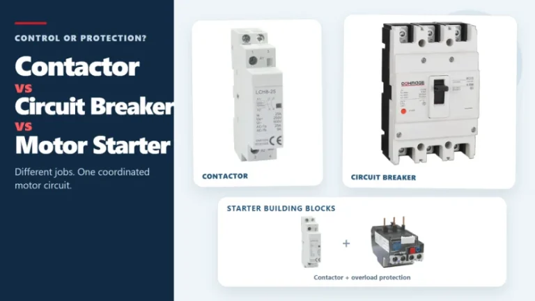
Figure 1. Contactors, circuit breakers, and motor starters solve different control and protection tasks. These three devices often appear in the same motor-control panel, but they solve different problems. A contactor handles frequent, remote, or automatic switching during normal operation. A circuit breaker interrupts abnormal current within its rated capability. A motor starter normally combines […]
Introduction The concept of remote tripping is simple, but in actual operation, project teams often encounter difficulties in specifying the components. The panel factory may require circuit breakers triggered by fire alarm relays, PLC outputs, building management system instructions, or other coordinated control. At this point, “diversion tripping” is only the first step in the […]
The main types of circuit breakers used in low-voltage distribution include miniature circuit breakers (MCBs), molded case circuit breakers (MCCBs) and residual-current devices such as RCCBs and RCBOs. They are not interchangeable. MCBs and MCCBs are selected for overcurrent protection in different circuit roles, an RCCB provides residual-current protection without integral overcurrent protection, and an […]