Voltage Transformers in Power Distribution: Types, Functions and Applications
Published: Author: Conor
Voltage transformers are a crucial component of today’s electrical power systems. They make the measurement, monitoring, and control of voltage possible safely and with accuracy in anything from utility substations to industrial facilities. Power distribution systems would face serious challenges in terms of efficiency and safety without them.
This guide provides an analysis of what voltage transformers are, how they work, their types and uses, common causes of mistakes, and what to consider when selecting the right device.
What is a Voltage Transformer?
A voltage transformer (VT) is a type of instrument transformer utilized to step down high system voltages to lower, standard voltages that can be safely operated on by measuring instruments, relays, and other control devices.
By doing so, VTs allow sensitive equipment to monitor or measure electrical parameters without being exposed to dangerously high voltages.
Voltage Transformers vs. Current Transformers
Both are critical for system protection and metering, but they serve different purposes: Voltage Transformer (VT)
Function: Steps down high voltage (e.g., from 11 kV to 110 V) for protection and safe measurement.
Wiring: Installed in parallel with the power line.
Output: Low-voltage signal proportional to the primary voltage.
Common Applications: Voltage measurement, synchronizing generators, detecting overvoltage or undervoltage conditions, power quality monitoring.
Function: Steps down high current (e.g., from 500 A to 5 A) for safe measurement and protection.
Connection: Installed in series with the power line.
Output: Low-current signal proportional to the primary current.
Typical Applications: Current measurement, overcurrent and short-circuit protection, load monitoring, fault detection.
VTs regulate voltage scaling and voltage-protection problems, while CTs regulate current scaling and current-protection problems. Both allow the control and measuring systems to function properly without being subjected directly to hazardous system conditions.
How Voltage Transformers Work in Power Distribution
Voltage transformers work on the basic principle of electromagnetic induction.
Primary winding— Supplied from the high-voltage side of the power system.
Secondary winding— Delivers a scaled-down voltage in proportion to the primary voltage.
Magnetic core— Provides a path for magnetic flux, enabling efficient induction.
When the AC voltage is applied to the primary winding, it induces a magnetic field in the core. The magnetic field induces a ratio voltage in the secondary winding. The voltage step-down factor is expressed by the primary to secondary windings ratio.
VTs, when used in distribution systems, are paralleled and feed their low-voltage output to metering instruments or protective relays. This enables safe, real-time monitoring and allows for rapid fault detection.
Types of Voltage Transformers
Voltage transformers are classified in numerous ways on the basis of their construction, voltage range within which they can operate, and the service they are intended to perform. Understanding these types of transformers helps in selecting the suitable transformer for your specific power distribution needs.
By Structure
a) Electromagnetic Voltage Transformers (EVTs)
Primary and secondary windings on a laminated steel core.
High accuracy, proven design, robust insulation.
Used widely in medium-voltage distribution systems.
Variants: single-phase EVTs for small systems; three-phase EVTs for compact three-phase measurement.
b) Capacitive Voltage Transformers (CVTs)
Combines a capacitor divider with an electromagnetic unit.
Cost-effective at high voltages; also couples carrier communication signals.
Common in high-voltage and extra-high-voltage (EHV) systems.
c) Optical Voltage Transformers (OVTs)
Use optical sensors and fiber optics to measure electric fields.
Lightweight, high isolation, immune to electromagnetic interference.
Favored in smart grids and digital substations.
By Operating Voltage
Low Voltage (<1 kV): Building automation, machinery monitoring.
Medium Voltage (1–72.5 kV): Distribution substations, industrial plants.
High Voltage (72.5–245 kV): Regional transmission, large industries.
Extra-High Voltage (>245 kV): Long-distance transmission, grid interconnection.
By Function
Measurement VTs: High accuracy for billing and energy audits.
Protection VTs: Reliable under fault conditions.
Combined Units: Perform both metering and protection.
Summary Table–Voltage Transformer Classification
Basis
Type
Typical Range
Applications
Structure
Electromagnetic (EVT)
LV, MV
Metering & protection in distribution
Capacitive (CVT)
HV, EHV
High-voltage lines, carrier communication
Optical (OVT)
MV, HV, EHV
Smart grids, EMI-sensitive sites
Operating Voltage
Low Voltage
<1 kV
Building automation, industrial monitoring
Medium Voltage
1–72.5 kV
Substations, industrial plants
High Voltage
72.5–245 kV
Transmission systems
Extra-High Voltage
>245 kV
Long-distance transmission, grid interconnections
Function
Measurement VT
All
Billing, accurate metering
Protection VT
All
Relay operation, safety
Combined Metering & Protection
All
Compact substation solutions
Key Functions in Power Distribution
Voltage transformers contribute to power distribution systems in several critical ways:
Metering Voltage Scaling: They transform high voltages to standard values, which can be safely measured by equipment.
Electrical Isolation: They isolate measurement circuits from the high-voltage side, protecting operators and equipment.
Supply of Signals for Protection Systems: They feed protective relays with accurate voltage data to detect faults like overvoltage, undervoltage, or phase imbalance.
System Monitoring: Continuous voltage data helps maintain stability and efficiency in the grid.
Common Errors in Voltage Transformers and How to Minimize Them
Even though voltage transformers (VTs) are designed to be precise, they are still subject to measurement errors. These inaccuracies can impact both metering accuracy and protective relay performance. Understanding the different types of errors helps engineers select the right transformer and maintain its accuracy over time.
Ratio Error: Proportionality deviation due to core loss, winding resistance, or burden mismatch.
Phase Angle Error: Small timing shift affecting power factor and relay accuracy.
Saturation Error: Core saturation under high or transient voltages.
Long-Term Drift: Accuracy changes over years due to insulation and core aging.
Voltage transformer errors are a function of both operating and design conditions. By selecting a proper accuracy class, burden control, and following good practices, these errors can be minimized to enable safe measurement and protection within the power system.
Applications of Voltage Transformers
Voltage transformers find their application in a wide range of settings:
Utility substations: Voltage measurement for control and protection systems.
Industrial facilities: Monitoring large motors, transformers, and switchgear.
Renewable energy plants: Integrating solar farms or wind turbines into the grid while ensuring safe voltage levels for monitoring equipment.
Commercial buildings: Managing load distribution and power quality in high-rise buildings.
Each application has its own accuracy and safety requirements, making proper selection critical. Example: VTs provide precise voltage data to ensure that inverters are synchronized with the grid properly and prevent potential instability within a solar farm.
Selection Criteria for Voltage Transformers
The choice of a suitable voltage transformer involves comparing some parameters:
Rated primary and secondary voltage: Must match system specifications.
Accuracy class: Determines permissible measurement error (high for billing metering, lower for protection).
Burden capacity: Secondary maximum load without exceeding error limits.
Insulation type: Air, oil, or resin cast, depending on environment and installation.
Environmental protection: IP rating for dust and moisture resistance.
Compliance with standards: IEC or locally equivalent.
Standardizing on a well-tested model in your project across several locations or voltage classes can make maintenance and spare parts easier.
Maintenance & Safety
Proper care extends the life of a voltage transformer and ensures safe operation. Routine practices:Visual examination: Inspect for cracks, corrosion, or loose connections. Cleaning: Dust off and remove dirt that may lead to tracking or excessive heating. Insulation testing: Periodic dielectric tests verify insulation integrity. Load checks: Confirm secondary burden remains within design limits. De-energizing before service: Always isolate and ground before maintenance work.
Outside installations, apply weatherproof enclosures or additional coatings for harsh environments.
Conclusion
Voltage transformers are essential for safe, accurate, and reliable power distribution. From scaling voltages for metering to feeding protective relays, they enable precise control of modern grids demand. Understanding their types, functions, and selection criteria helps ensure you get the right equipment for your needs.
For any project — whether building a new substation or upgrading industrial power systems — selecting a high-quality VT matched to your needs ensures long-term reliability and safety. OOHMAGE is a trusted name in the electrical component industry, known for producing high-quality isolator switches, RCBOs, surge protection devices, and more. With a strong emphasis on safety, durability, and performance, OOHMAGE products are widely relied upon across residential, commercial, and industrial applications.
FAQs
What’s the difference between a voltage transformer and a current transformer?
A voltage transformer (VT) steps down high voltage to a lower, standardized level suitable for meters and protective relays, and is connected in parallel with the circuit. A current transformer (CT), on the other hand, steps down high current to a safe level and is connected in series with the circuit. Both provide isolation, protect measurement devices, and support accurate monitoring, but they measure different electrical quantities.
How do I know if my voltage transformer is faulty?
Common warning signs include:
Inaccurate meter readings despite calibration of measuring devices.
Overheating or unusual humming noise.
Visible damage to the enclosure or insulation.
Oil leakage in oil-filled VTs.
Abnormal relay operation during fault conditions.
If any of these are detected, take the VT out of service and perform diagnostic tests such as turns ratio test, insulation resistance test, or power factor test.
What’s the difference between a measuring VT and a protection VT?
Measuring VT: Optimized for high accuracy under normal operating conditions; used for metering and monitoring.
Protection VT: Designed to maintain performance during fault conditions, even if accuracy slightly drops during normal operation. Often built to withstand higher overvoltages and transient stresses.
Some modern VTs are combined units that can serve both purposes, saving space and cost.
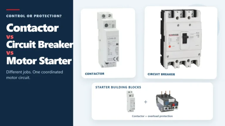
Figure 1. Contactors, circuit breakers, and motor starters solve different control and protection tasks. These three devices often appear in the same motor-control panel, but they solve different problems. A contactor handles frequent, remote, or automatic switching during normal operation. A circuit breaker interrupts abnormal current within its rated capability. A motor starter normally combines […]
The main types of circuit breakers used in low-voltage distribution include miniature circuit breakers (MCBs), molded case circuit breakers (MCCBs) and residual-current devices such as RCCBs and RCBOs. They are not interchangeable. MCBs and MCCBs are selected for overcurrent protection in different circuit roles, an RCCB provides residual-current protection without integral overcurrent protection, and an […]
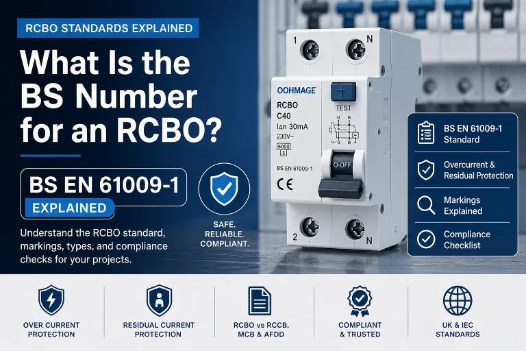
Introduction If you are searching for the RCBO BS number, the answer most commonly required in UK and IEC-based electrical procurement is BS EN 61009-1. This is the principal product standard associated with residual current circuit breakers with overcurrent protection used in residential, commercial, and similar installations. However, merely the BS number is not sufficient […]


 Voltage transformers contribute to power distribution systems in several critical ways: