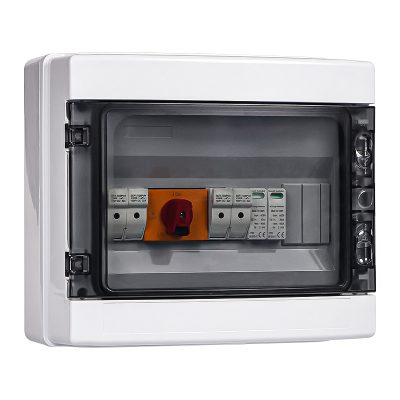
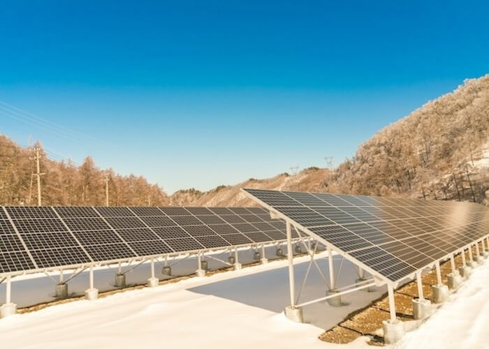
In PV systems, a solar combiner box brings selected photovoltaic (PV) string circuits into a defined output arrangement and can house protection, isolation or monitoring equipment. Whether a separate box is needed depends on the inverter inputs and the project design.
For buyers, a clear combiner box drawing makes string grouping, component ratings and inverter compatibility easier to check before ordering.
This guide explains common components and how to review a DC PV combiner box diagram. It is a design-reading reference; installation and commissioning require qualified personnel, the equipment instructions and the applicable project requirements.
Quick wiring overview: a typical PV combiner box wiring diagram shows string inputs, fuses or DC breakers, busbars, grounding, surge protection and one or more outputs to the inverter. Before specifying a combiner box, confirm the number of strings, system voltage, current rating, protection devices and enclosure requirements.
Read related articles to learn more about solar combiner boxes:
A wiring diagram helps reviewers trace connections, protection and output grouping. Check that it identifies the equipment model and drawing revision. A conceptual diagram alone does not establish that an installation is safe or compliant.
DC PV Combiner Box Components
A DC PV combiner box typically consists of several important parts that all combine to make sure your solar power system operates efficiently and safely. The following is a description of the most important parts:
PV combiner box enclosure
The casing is the housing for all the components within. It is usually constructed of plastic or metal to shield the system from the environment like rain, dust, and excessive sunlight. This housing shields the system from damage and non-functionality over time.
Fuses and Circuit Breakers
Fuses and circuit breakers are important parts of overcurrent protection. They must be selected and coordinated with the PV string and the inverter to interrupt fault or reverse current within their declared voltage, current, and breaking-capacity ratings. A DC fuse typically needs to be replaced after it is blown, whereas circuit breakers can be reset once the cause of the trip has been identified and cleared.
Busbars and Terminal Strips
Busbars provide conductive paths for the circuits assigned to them. Terminal blocks provide conductor connection points with conductive contacts and insulating supports. Their current, voltage, conductor-size and environmental ratings must match the design; the housing material alone does not establish suitability.
Grounding
Earthing and equipotential bonding must follow the equipment instructions and the project design. The drawing should identify the protective connections required for exposed conductive parts. Do not assume that the PV negative conductor and protective earth are interchangeable.
Surge Protection Devices (SPDs)
PV-rated surge protective devices limit transient overvoltages according to their declared application and connection arrangement. Check the specified PV voltage, protection configuration and earthing connections against the product instructions.
For the surge-protection stage of a PV combiner design, review OOHMAGE surge protection devices and confirm the PV DC-side voltage, Type 1+2 or Type 2 requirements, pole configuration and discharge-current ratings before quotation. Surge protection on the AC side belongs to the AC installation rather than to the combiner box.
Wiring diagrams can come in two main formats: pictorial and schematic.
Pictorial Diagrams
A pictorial diagram uses simple-to-visualized images and representations of components, making it extremely easy to comprehend for those with little experience with electrical systems.
A pictorial diagram illustrates the arrangement of the equipment shown. Use the supplied model-specific drawing and terminal markings to confirm actual connections.
Schematic Diagrams
A schematic diagram, however, uses symbols for the hardware and wiring. This type is more technical and assumes some familiarity with electrical symbols and system operation. But to experts or hands-on practitioners, schematic diagrams prove most useful.
How to Read and Interpret a Wiring Diagram
Reading a wiring diagram of a solar combiner box is an essential skill for anyone who works on solar system installation or maintenance. The diagram will typically show:
Input and Output Connections: It shows how the wires from the solar panels are connected to the combiner box and then to the inverter or battery.
Circuit Protection: Schematic diagrams will usually show where the DC circuit breakers and fuses are located in relation to the system.
Grounding Points: Symbols are specifically given for grounding connection points to allow for safety.
Common Symbols in Wiring Diagrams
Use the drawing legend to identify fuses, circuit breakers, disconnectors, busbars and protective-earth connections. Confirm unfamiliar symbols against the referenced drawing standard; do not infer a device’s switching or isolation capability from its symbol alone.
Before Installation: Review the Drawing and Documents
Use the drawing to resolve specification questions before work begins. The checklist below supports design and procurement review; it is not an installation sequence.
The third-party video illustrates one arrangement. Its connections are not a universal wiring procedure for other equipment or projects.
Confirm the Equipment and Output Groups
Identify the exact combiner model, drawing revision, PV string inputs and inverter inputs. Check which circuits are combined and which remain separate for the intended MPPT arrangement. Do not assume all negative conductors belong on a common busbar.
Check Five Items Before Accepting the Drawing
Inputs and outputs: string count, circuit labels, output grouping and the intended inverter input arrangement.
Protection devices: fuse or breaker model, declared DC ratings and the protection arrangement required by the design.
Isolation boundaries: which disconnecting device controls each circuit and which parts may remain energized.
Equipment instructions: terminal identification, permitted conductors, connector compatibility and the manufacturer’s specified termination requirements.
Inspection and commissioning: the project test plan, responsible qualified personnel and the records required before handover.
Recognize the PV Voltage Hazard
PV modules can generate hazardous DC voltage whenever exposed to light. Switching off an inverter does not by itself establish that the array wiring is de-energized. Qualified personnel must follow the equipment-specific isolation and verification procedure. See the SMA safety guidance for an example of this hazard; its product-specific procedure must not be substituted for your equipment instructions.
Commissioning must follow the project inspection and test plan, including the required checks of protective connections, polarity, terminations and insulation. A general article cannot determine the sequence of electrical work.
Common Mistakes to Avoid During Solar Combiner Box Wiring
Incorrect polarity or circuit grouping: compare the circuit labels and positive/negative paths with the approved drawing and inverter input arrangement.
Undersized conductors can overheat and create excessive voltage drop. Cable selection requires the circuit design current, installation conditions, applicable correction factors and equipment terminal limits.
Poor Grounding Practices: Poor grounding can increase the risk of electric shock or fire. Follow the equipment manufacturer’s instructions and the approved project design when selecting and installing grounding and bonding arrangements.
There are other issues when dealing with solar combiner boxes, check this article:
Cable sizing: review design current, routing, ambient conditions, grouping, allowable voltage drop, insulation rating and terminal compatibility. A string count or a small/large system label is insufficient to select a conductor size.
Sealing and Weatherproofing: For external installations, check that all inlet and outlet points are closed to the enclosure’s declared ingress-protection (IP) rating, and confirm that rating against the product instructions.
Labeling and Marking Connections: Label every component and wire in the combiner box. This will make it easy to service the system in the future and ensure that anybody working on the system can readily recognize components.
Conclusion
A useful combiner box diagram connects the equipment list to the string arrangement, protection strategy and inverter inputs. Review those items together before ordering or installation.
Send your string count, maximum system voltage, circuit currents, output grouping and installation environment with your enquiry. This gives the supplier a clear basis for checking the proposed configuration and identifying missing information.
About OOHMAGE
OOHMAGE manufactures and supplies low-voltage electrical products for overseas distributors, project buyers and professional customers.
OOHMAGE supports product selection, OEM/ODM packaging, outgoing inspection and export order coordination according to the confirmed product and order requirements.
Certification and technical document support can be provided according to the confirmed product series and order requirements. Contact us with your application and product requirements.
FAQ
How do I wire a DC PV combiner box?
There is no universal connection sequence for every DC PV combiner box. The installer must follow the approved model-specific drawing and equipment instructions. For design review, identify string inputs, protection, output grouping, earthing and the intended inverter inputs before accepting the drawing.
How to read a solar combiner box wiring diagram?
To read a solar combiner box wiring diagram, first identify the input and output terminals of every string of solar panels.
The diagram will show the electrical protective devices (e.g., fuses or circuit breakers), busbar connections, and wiring routes for the positive and negative terminals. Understanding basic electrical symbols will allow you to read the diagram correctly.
How to choose the wire size for a solar combiner box?
Select conductor size from the electrical design and installation conditions, including circuit current, temperature, grouping, voltage drop and terminal limits.
Do not select a fixed AWG size solely from whether a PV system is described as small or large. Use the project cable calculation and the applicable equipment instructions.
Can a solar combiner box be used for both DC and AC systems?
A solar combiner box is a DC-side assembly used to combine outputs from multiple PV strings before the inverter. Where AC outputs must be combined downstream of string inverters, use a separate AC-side combiner or distribution assembly with ratings and protection suitable for that duty. Do not treat AC and DC combiner assemblies as interchangeable.
AC and DC combiner assemblies have different duties and component requirements. Do not assume an assembly is interchangeable between AC and DC applications.
What is the difference between a solar combiner box and a junction box?
A solar combiner box is applied to merge multiple strings of solar panels into a single output, typically before the DC power is fed to an inverter. It has protection devices such as fuses or circuit breakers.
Junction boxes are also used in photovoltaic systems, including on PV modules. The useful distinction is function: a string combiner provides the input/output arrangement and protection specified for the array, while a junction box provides the connections for its particular application.
Only “solarcombiner box” in your quotation is far from sufficient. What should be connected to the box? A PV string or an inverter output? They match different jobs. The price and enclosure size can be considered at a later stage. What connects to the input is the top priority. To be more specific, a DC combiner […]
What is a combiner box? In solar power systems, a PV combiner box plays a critical role. It simplifies the connection of multiple solar panel arrays to the inverter. It guarantees efficient power management, safety, and scalability. To choose the right PV combiner box supplier, you should have a basic idea of the product. Follow […]
An electrical distribution board receives an incoming electrical supply and organizes power distribution to outgoing circuits. Depending on the design, it may contain a main switching device, busbars, circuit breakers, residual-current protection, terminals, internal wiring and labels inside a suitable enclosure. The terms distribution board, distribution box, consumer unit and panelboard are not used identically […]