The knowledge of circuit breaker symbols is imperative for electrical designers, installers, and maintenance personnel. Indeed, circuit breaker symbols form that universal language on electrical schematics, through which clarity and safety across a wide spectrum of applications can be possible. The detailed study will attempt to review with copious detail the circuit breaker symbols.
What Are Circuit Breaker Symbols?
Circuit breaker symbols are standardized graphical representations that are used in electrical diagrams for the identification of the existence and function of circuit breakers.
They give, in a very simplified manner, complex information on electrical circuits to help in understanding and communication by engineers, electricians, and technicians.
There are several types of circuit breakers applied in electrical systems, and they come with different symbols:
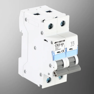
Miniature Circuit Breaker (MCB)
Miniature circuit breaker manufacturers produce them for low voltage circuits to handle overcurrent and short circuits. They find their applications in residential and light commercial usage.
Symbol: The MCB symbol generally consists of a small rectangle that is intersected by a line, showing the breaking mechanism. This standard symbol makes it easy to identify in circuit diagrams.
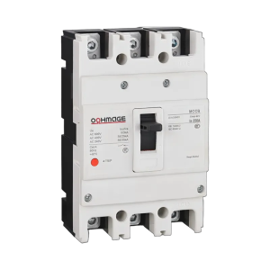
Molded Case Circuit Breaker (MCCB)
Molded case circuit breakers are higher-rated current and can carry on with loads heavier than MCBs. They provide protection for overloads, short circuits, and ground faults, finding their applications in industries and big commercial sectors.
Symbol: The MCCB symbol is essentially a rectangle with rounded corners, often with a diagonal line or zigzag pattern inside to indicate its breaking function. This reflects the robust construction and functionality of the breaker.
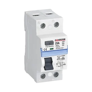
Residual Current Circuit Breaker (RCCB)
A residual current circuit breaker detects earth faults by measuring the difference between live and neutral currents. In case of an imbalance, which indicates a leakage current, the RCCB disconnects the circuit for the avoidance of electric shock hazards.
Symbol: The RCCB symbol is represented by a rectangle with a test button symbol inside, signifying its ability to detect and test residual currents. This symbol highlights the safety features inherent in RCCBs.
Standardization of Electrical Symbols
Standardization bodies such as the International Electrotechnical Commission and American National Standards Institute have developed standards for electrical symbols, including:
IEC Standards: Most widely applied internationally, IEC symbols offer a standardized way of approaching electrical schematics with consistency and safety.
ANSI Standards: Mainly used in the United States, ANSI symbols are targeted to meet regional practices and compliance requirements.
How to Read and Interpret Circuit Breaker Symbols
Understanding circuit breaker symbols requires an understanding of the shapes, lines, and annotations of the symbols:
Identify the Basic Shape
Rectangles or Squares: The common geometric shapes for circuit breakers in diagrams are rectangles or squares. In most cases, the shape may refer to the type of breaker it is. A usual example is that a rectangle with rounded corners normally represents an MCCB.
Look for Intersecting Lines
Diagonal or Zigzag Lines: Lines through or crossing the main figure indicate the breaking method. The diagonal line will suggest a standard circuit breaker while the zigzag may symbolize a fuse or a particular type of breaker that displays unique interrupting capability.
Other Markings
Letters and Numbers: Letters detail important information on the breaker’s ratings. For example, letters like ‘B’, ‘C’, or ‘D’ may refer to the tripping characteristics of MCBs-manifesting their response to overcurrent conditions. Numbers can indicate current ratings or voltage levels, hence giving an idea of capacity and application areas.
Common Mistakes and Misinterpretations
1. Overlooking Standard Variations
Electrical schematics adhere to various international standards, such as IEC, ANSI, and IEEE, each with distinct symbol conventions. Misinterpreting these symbols can result in incorrect component identification.
A circuit breaker symbol in IEC standards may differ from that in ANSI standards. Familiarity with the specific standard in use is essential to prevent misinterpretation.
The standard on which the schematic is based should always be checked. Use standardization documents or guides for the correct interpretation of the symbols.
2. Ignoring Annotations
Annotations carry crucial information regarding a circuit breaker’s specifications, such as current rating, voltage rating, and tripping characteristics. Failure to consider such information may lead to incorrect selection or application.
An ‘A’ might designate an amperage rating, and a ‘B’, ‘C’, or ‘D’ might designate tripping curves. Misreading these may result in choosing a breaker unsuitable for the circuit requirements.
Be aware of all the annotations that come with the symbols. Look to the manufacturer’s datasheet or standard references for interpretation correctly.
3. Misinterpreting Symbol Elements
Circuit breaker symbols are made up of different elements such as rectangles, lines, and arcs carrying specific information in the functionality and nature of the breaker.
A rectangle with a diagonal line may represent a standard circuit breaker, while additional symbols like arcs or dots can indicate features like arc suppression or specific breaking capacities.
Study what makes up a circuit breaker symbol and what each part of it means. Use reference materials or guides listing those elements to correctly interpret them.
4. Missing Contextual Clues
Symbols should be interpreted in the context of the whole schematic. A symbol that is considered in isolation, without taking into consideration the surrounding components and their connections, can be misunderstood.
A circuit breaker symbol placed next to a transformer symbol could indicate that it serves a special protective function, which would affect its ratings.
Look at the symbols in the context of the entire drawing. Think about how each component functions in the system to correctly interpret its function and ratings.
5. Overlooking in Standard Updates
Electrical standards and symbol conventions can evolve over time. Relying on outdated information may lead to misinterpretation of current schematics.
Stay informed about updates in relevant electrical standards. Regularly consult the latest versions of standardization documents to ensure compliance and accurate interpretation.
Practical Applications of Circuit Breaker Symbols
Design
Precise Planning: Standardized circuit breaker symbols enable the engineers to effectively plan the electrical layout in minute detail, thus allowing them to incorporate protective devices appropriately to avoid faults.
Standardization: The use of standardized symbols means the design will be according to standards and regulations; hence, this makes communication easy among professionals and stakeholders.
Installation
Guidance for Technicians: The clear symbols pave the way for electricians to apply the circuit breakers correctly in the system. This accuracy reduces mistakes during installation and enhances the general reliability of the system.
Efficient Workflow: Well-documented diagrams with accurate symbols ease the installation process and save the time and effort needed to interpret complicated circuits.
Maintenance
Easy Fault Finding: Schematics with detailed symbols allow maintenance personnel to quickly identify circuit breakers and their location, hence they can diagnose and solve the problem efficiently. This reduces the system’s downtime.
Safety Assurance: Symbols accurately help in understanding the configuration of the system; this ensures that maintenance work is safely conducted by clearly indicating the presence and type of circuit breakers.
Final Thoughts
Understanding circuit breaker symbols is absolutely necessary within the field of electrical systems. Full understanding means safety, compliance, and efficiency in design, installation, and maintenance. As long as technology and standards keep evolving, so does the need for continuous learning to stay proficient in interpreting these vital symbols.
Keep following OOHMAGE blogs and learn more about different types of electrical equipment. Or you can read other related articles:
What is the purpose of circuit breaker symbols in electrical diagrams?
Circuit breaker symbols are standardized presentations of circuit breakers in electrical schematics that make communication among engineers, electricians, and technicians effective. They denote the existence and type of circuit breakers within a circuit; thus, they help in design, installation, and maintenance processes.
How do MCB symbols differ from other circuit breaker symbols?
The MCB symbol is usually represented by a small rectangle with a horizontal line through it, showing the breaking mechanism. Other breaker symbols, like MCCBs, are usually represented by a rectangle with rounded corners and sometimes other marks showing what function they perform.
Why is the standardization of electrical symbols important?
Standardization means consistency and uniformity in electrical diagrams to reduce the possibility of misinterpretation. This makes it easy for professionals from different regions and industries to understand and work with electrical schematics easily for safety and international standardization.
How to interpret circuit breaker symbols accurately?
Familiarization with the resources of standardization bodies such as the IEC and ANSI will be helpful. Also, the study of electrical schemes, relevant courses, and handbooks will help one to be more confident.
Are circuit breaker symbols different in different countries?
Yes, even though most symbols are standardized internationally, there are some variations depending on the regional standards and practices. It is always necessary to know what standards apply in your region or in the region where the electrical system will be applied.
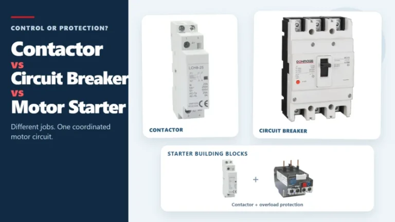
Figure 1. Contactors, circuit breakers, and motor starters solve different control and protection tasks. These three devices often appear in the same motor-control panel, but they solve different problems. A contactor handles frequent, remote, or automatic switching during normal operation. A circuit breaker interrupts abnormal current within its rated capability. A motor starter normally combines […]
Introduction The concept of remote tripping is simple, but in actual operation, project teams often encounter difficulties in specifying the components. The panel factory may require circuit breakers triggered by fire alarm relays, PLC outputs, building management system instructions, or other coordinated control. At this point, “diversion tripping” is only the first step in the […]
The main types of circuit breakers used in low-voltage distribution include miniature circuit breakers (MCBs), molded case circuit breakers (MCCBs) and residual-current devices such as RCCBs and RCBOs. They are not interchangeable. MCBs and MCCBs are selected for overcurrent protection in different circuit roles, an RCCB provides residual-current protection without integral overcurrent protection, and an […]