How to Wire & Install an RCBO: A Step-by-Step Electrical Guide
Published: Author: Joanna
Introduction
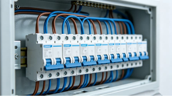
RCBO (Residual Current Breaker with Overcurrent Protection Function) provides independent leakage protection and overcurrent protection for each end circuit. This means that the lighting circuit, socket circuit, kitchen circuit or electrical circuit can trip independently without causing the power supply of half of the circuits in the distribution box to be simultaneously cut off.
Replacing the old double-RCD distribution box with a fully-configured RCBO distribution box is a common upgrade solution. In the old layout, if a certain electrical appliance has a leakage current problem, it may cause multiple normal circuits to trip; while the modern RCBO layout can limit the fault range to a single circuit, making the inspection, reset and maintenance work much simpler.
This guide, from a professional perspective, explains how to install RCBOs in distribution boxes. The content covers isolation, installation, power connection, load terminal connection, functional grounding wiring, testing, and common wiring errors that inspectors often encounter during the acceptance process.
The work described in this article is carried out at the low-voltage user terminal equipment or distribution box. Such work is only permitted to be performed by personnel with the corresponding qualifications, and all installation decisions must comply with local wiring specifications, manufacturer instructions and inspection requirements.
RCBO Fundamentals & Wiring Precision
RCBO Meaning in Practical Circuit Protection
RCBO combines the functions of MCB (Miniature Circuit Breaker) and RCD (Residual Current Device). Among them, the main function of MCB is to deal with situations of overload and short-circuit current; the function of RCD is to deal with the problem that the current flowing through the conductor of the line cannot flow evenly through the neutral line.
In a single-phase installation, connecting the correct RCBO will monitor the phase wire (hot wire) and neutral wire (zero wire) of a single circuit. When leakage current flows to the ground due to damaged insulation, moisture, equipment failure, or accidental human contact, as soon as the remaining current reaches the trip threshold, the RCBO can cut off the circuit.
Most household and light commercial residual current operated circuit breakers (RCBOs) are set with a residual current rating of 30mA to provide additional protection against electric shock. When designing the circuit, it is still necessary to reasonably select the rated parameters, tripping curves, breaking capacity, and residual current type of the equipment.
Core Tools and Safety Preparations Before Installation
Required Tools and Equipment
Before opening the distribution box, make sure to prepare the necessary tools and safety equipment. To achieve a neat and standardized RCBO installation, the key lies in controlled cable stripping, precise torque control, verified power isolation, and meticulous cable arrangement.
Calibrated two-pole voltage tester and proving unit for safe isolation checks
Lock-off kit, warning tag, and suitable isolation device for the main switch or upstream supply
Insulated screwdrivers, including a torque screwdriver set to the manufacturer’s specified Nm value
Wire strippers suitable for the conductor sizes used in the circuit
Side cutters and long-nose pliers for dressing conductors without damaging insulation
Multi-function tester for continuity, insulation resistance, loop impedance, polarity, and RCD trip-time testing
Manufacturer’s data sheet for terminal markings, torque values, device type, and wiring diagram
PPE suitable for the working environment, including eye protection where required
Safe Isolation Comes Before Any Wiring Work
Before safely disconnecting the power supply of the user’s distribution box, installation of the RCBO is not allowed. The operation steps include: cutting off the power supply, locking it, hanging warning signs, and before use, it is necessary to use a voltage detector to test the known live power supply to ensure its normal operation.
After opening the distribution box, test the voltages between the live wire and the neutral wire, the live wire and the ground wire, as well as the neutral wire and the ground wire separately. Then, recheck whether the tester is functioning properly. This method reduces the risks caused by faulty testers or incorrect circuit markings to a certain extent.
Before dismantling the wires, please first check the layout of the circuit board. Identify the target circuit, its conductive wires, neutral wire conductors, CPC or grounding conductors, as well as any existing RCD group connections. It is best to mark the circuit before disconnecting the connections, which helps prevent wiring errors when upgrading and installing the RCBO.
The Step-by-Step Installation Process
Physical Installation Sequence
The specific terminal layouts of different brands vary. Some RCBOs adopt an external neutral wire (fly wire) design, while some newer distribution boxes use plug-in neutral wire connection devices. Additionally, the power terminals of some products are located at the bottom, while others are at the top. Before making the connections, be sure to refer to the wiring diagram printed on the equipment itself.
The following steps illustrate how to wire and install an RCBO protection device in a typical single-phase user distribution box, while ensuring that this method is applicable to the common distribution layouts commonly used in the UK and the European Union.
Isolate the consumer unit and confirm the circuit identity. Switch off the main isolator or upstream protective device, apply a lock-off device, and verify dead with a two-pole tester. Confirm the final circuit you plan to protect. Trace the line, neutral, and CPC so the RCBO monitors the correct pair of live conductors.
Remove the existing protective device if replacing an MCB. Loosen the outgoing line terminal, release the device from the DIN rail, and separate the circuit neutral from the old neutral bar or RCD neutral terminal. Keep the conductors grouped so the line and neutral from the same circuit remain together.
Mount the RCBO onto the DIN rail.Securely insert the equipment into its proper position and ensure it aligns with the connection point of the busbar. The locking mechanism should be able to engage smoothly without the need for forceful operation. If the busbar is not aligned, it may result in insufficient contact pressure, overheating, or intermittent power supply.
Connect the supply side according to the device design. For standard distribution boxes, the live power supply is usually connected to the incoming terminal through the busbar. For distribution boxes with plug-in zero-line busbars, electrical components can be directly connected to the live and neutral busbars. For RCBOs with lead-out wires (fly wires), the neutral lead-out wire should be neatly routed and connected to the correct neutral busbar as specified by the manufacturer.
Prepare the load conductors. Strip the outgoing brown line conductor and blue neutral conductor to the manufacturer’s recommended length, often around 10mm to 12mm. Avoid nicking copper strands or leaving exposed copper outside the terminal mouth. Where fine-stranded conductors appear, use suitable ferrules only when the manufacturer permits them.
Terminate the outgoing line and neutral into the RCBO load terminals. Connect the live wire (hot wire) to the L-Out terminal and the neutral wire to the N-Out terminal. This answers the question of how to connect an RCBO in the actual field: The two load conductors must pass through the same RCBO sensing mechanism, rather than through separate neutral wire racks or other circuit terminals.
Terminate the functional earth fly-lead where applicable. Some RCBOs include a white functional earth lead. Route this conductor cleanly to the main earth terminal block or the manufacturer’s specified earth connection point. Do not confuse this conductor with the circuit CPC. It supports device operation and testing, but it does not replace the protective earth conductor of the final circuit.
Torque, dress, label, and inspect the installation. Tighten each terminal to the stated torque value, commonly around 2.0Nm to 2.5Nm for many consumer-unit devices, though the manufacturer’s data always takes priority. Dress conductors so they do not strain terminals. Label the circuit clearly, replace covers correctly, and confirm that no copper remains exposed.
Avoiding Neutral Errors During Installation
When upgrading the distribution box and installing RCBOs, the handling of the neutral circuit is often the most challenging part. Traditional MCBs usually only switch and protect the live conductor, while the neutral line returns through a shared neutral busbar.
The RCBO must simultaneously monitor both the live wire and the neutral wire in the circuit. If only the phase wire is moved from the MCB to the RCBO, from the perspective of residual current monitoring, the circuit will not be able to form a complete loop. Therefore, the corresponding circuit neutral wire must be connected to the RCBO or connected to the correct plug-in neutral line system.
Always keep the live wire and the neutral wire of the same circuit connected throughout. Do not simply “borrow” the nearby neutral wire just because it seems convenient or because there is an available neutral terminal at a certain location. This practice often leads to false tripping and may mask more serious wiring defects.
Post-Installation Testing & Verification
Initial Visual and Mechanical Checks
Before powering on, a test is required. Please check whether all the equipment is installed straightly on the DIN rails, whether the busbar connections are in place, and whether there are any loose or incorrect screw fastening phenomena on the terminal screws. At the same time, confirm that the circuit markings match the outgoing cables.
Check the stripping length of the wires. The copper conductor should be fully placed inside the terminal crimping frame, and the insulation layer should not be trapped beneath the crimping area. After tightening the screws, gently pull each wire to confirm that it is firmly connected.
Polarity check is also crucial. Make sure that the phase wire (hot wire) and the neutral wire are respectively connected to the correct power terminals and load terminals. When the wiring is incorrect, the equipment may still be able to operate normally on the surface, but potential safety hazards can be discovered through inspection and testing.
Functional Testing and Trip-Time Verification
After re-powering under controlled conditions, press the test button of the RCBO. This button will create an internal imbalance state to test whether the residual current actuating mechanism will trip. Although this button cannot replace a complete installation test, it can confirm whether the mechanical trip function is responding normally.
Then, a calibrated multi-function tester should be used to verify the performance of the residual current circuit breaker (RCD). For a common 30mA RCBO, electricians usually check its tripping action under the rated residual operating current and five times of this value according to relevant specifications and the settings of the testing instrument.
Regarding the question “How to test RCBO”, its scope is not limited to using the test button; it also includes various verifications of the circuit. If necessary, check the conductivity of the protective conductor, insulation resistance, polarity, grounding fault circuit impedance, and the expected fault current, and record the test results in the corresponding certificate or inspection report.
Newly installed RCBOs should not be regarded as a substitute for fault diagnosis. If the equipment trips during testing or during load operation, check the circuit and do not repeatedly perform reset operations.
Common Wiring Mistakes & Prevention
Shared or Borrowed Neutrals
Borrowed neutrals appear when a circuit takes line from one protective device but returns neutral through another circuit path. In an RCBO board, that imbalance usually trips the device as soon as the load starts.
This issue often appears during consumer-unit upgrades, especially in older lighting circuits, two-way switching arrangements, altered ring circuits, and poorly documented extensions. Careful circuit tracing and continuity testing help identify the problem before the board goes back into service.
When learning how to correctly connect an RCBO, please keep in mind this principle: The RCBO must monitor all the incoming and outgoing currents flowing through the specific circuit. If any current returns via other paths, the device will determine this difference as an electrical leakage.
Incorrect Torque Settings
Loose terminals create heat. Over-tightened terminals can damage conductors, crush copper, or strip threads. Both conditions reduce reliability and may leave visible signs during later thermal inspection.
Please use a torque screwdriver instead of estimating by hand. Although the specified values vary among different manufacturers, the torque values for many equipment inside distribution boxes are usually between 2.0 Nm and 2.5 Nm. The values marked on the equipment or the parameters in the product data sheet should be taken as the final basis, taking precedence over any conventional operating practices.
Recheck conductors after dressing the wiring. Pulling a conductor into a neat route after tightening can introduce mechanical stress. Good workmanship leaves the terminal carrying electrical current, not physical tension.
Line and Neutral Reversal
The terminal markings of RCBO are of great importance. The design directions of the power supply end and the load end of different devices may vary. A few compact RCBOs adopt specific marking methods that are different from the traditional MCB layout.
When installing, one should follow the wiring diagram on the side of the equipment instead of referring to the layout of the original circuit breaker. If the installation involves the insertion of the neutral line bus, it is essential to confirm its compatibility with the specific distribution box series. Even if the equipment can be physically installed in place, if it does not match the distribution box system, it may still not function properly.
Reverse polarity can lead to failed inspection results and unsafe maintenance conditions. Therefore, it is necessary to verify the polarity after wiring and before delivery for use.
Wrong RCBO Type for the Load
Modern electrical loads often contain electronic power supplies, variable-speed drives, LED drivers, induction hobs, washing machines, heat pumps, and EV charging equipment. These loads may produce DC components or complex leakage waveforms.
Type AC devices respond to sinusoidal AC residual current. Type A devices respond to AC and pulsating DC residual currents. More specialized applications may require Type F or Type B protection depending on equipment design and local requirements.
Selection should come before installation. Knowing how to install a rcbo physically does not remove the need to match the residual-current type, current rating, tripping curve, and breaking capacity to the circuit.
Final Thoughts
To correctly connect an RCBO, one needs to understand both its physical terminals and its protection logic. This device must monitor the complete live path of a circuit, including the output live wire and neutral wire. Additionally, it must be properly installed on the busbar, fastened the wires with the specified torque, and successfully pass all necessary verification tests.
For the contractor, this operation process should be a repeatable and standardized procedure: identifying circuits, ensuring safety isolation, installing equipment, connecting power supply, connecting load lines and neutral lines, laying functional grounding wires (if applicable), tightening terminals according to specified torque, conducting tests, recording data and attaching labels.
For maintenance managers, the advantages are particularly prominent during the fault response stage. A well-designed RCBO distribution panel can isolate the specific circuit that has failed, and it does not require the power supply of other unrelated circuits such as lighting, cooling, IT equipment, or office power to be cut off.
RCBO Installation FAQs
Can you mix standard MCBs and RCBOs in the same consumer unit?
Yes, some distribution boxes allow for the mixed installation of MCB and RCBO, but these devices must be compatible with the distribution box, and the protection design must also comply with the relevant wiring standards. Each RCBO circuit requires its own correct neutral wire path.
Why does my newly installed RCBO trip instantly when the appliance is turned on?
The most common causes include using the neutral wire, reversing the connection of the live wire and the neutral wire, insulation leakage, circuit moisture, or electrical malfunction. Disconnect the load, test the circuit, and confirm that the live wire and neutral wire both pass through the same residual current action circuit breaker (RCBO).
Do RCBOs protect against both short circuits and earth leakage?
Yes. An RCBO combines overcurrent protection and residual-current protection. It can trip for overload, short circuit, or earth leakage, depending on the fault condition and device rating.
What is the purpose of the white fly-lead on an RCBO?
The white fly-lead, where fitted, usually acts as a functional earth connection for the device electronics or test circuit. It should connect to the manufacturer’s specified earth terminal, but it does not replace the circuit protective conductor.
How do you wire a RCBO in a plug-on neutral consumer unit?
The plug-in neutral circuit RCBO is connected to the phase and neutral busbar system of the distribution box through a specific installation structure; however, the phase and neutral lines of the outgoing circuit still need to be connected to the load terminals of the RCBO according to the equipment markings.
How to connect a RCBO when replacing an old MCB?
Remove the old miniature circuit breaker (MCB) wiring connections, identify the corresponding neutral line of the circuit, install the residual current operated circuit breaker (RCBO), connect the power side, and connect both the phase wire and neutral wire at the outlet end to the RCBO. Unless explicitly required by the power distribution system, do not retain the neutral line of this circuit on the old common neutral bus.
Brand Introduction
OOHMAGE provides electrical protection solutions including RCCBs, electrical switches, and related protection devices for residential, commercial, and industrial electrical systems.
A single-line diagram can look simple and still be difficult to read. One line may represent a multiphase circuit, a small symbol may stand for a major protective device, and a short label may carry the information that determines what equipment belongs downstream. The most reliable way to read a single-line diagram is to follow […]
Figure 1. Three-phase SPD selection starts with system facts, not the largest kA number. A three-phase surge protector should not be selected by the largest kA number on its label. First confirm the system voltage, whether a neutral is present, the earthing arrangement, the installation point, and the required SPD type. Then compare Uc, Up, […]
An AC-only miniature circuit-breaker,you cannot treat it as a DC circuit by default.Confirm before using: If the manufacturer explicitly rates the selected model for the required DC voltage, pole arrangement, polarity where applicable, fault current, and breaking capacity.Some breakers carry both AC and DC ratings, but these alone cannot reflect the actual situation. If the […]