How to Test and Replace a Faulty Fuse Holder: AC Fuse Holder and Amp Fuse Holder Diagnostics
Published: Author: Joanna
Introduction
Reliable circuit protection components and their mechanical housings form the critical backbone of industrial electrical safety. In modern power distribution networks, continuous high-amperage loads and aggressive thermal cycling inevitably accelerate the degradation of component housings. Over time, these operational stressors demand precise, analytical diagnostic strategies rather than the archaic approach of simple part-swapping.
This guide provides an objective, highly technical exploration of the rigorous testing protocols and exact replacement criteria required for industrial electrical protection, ensuring facility uptime and mitigating catastrophic failures.
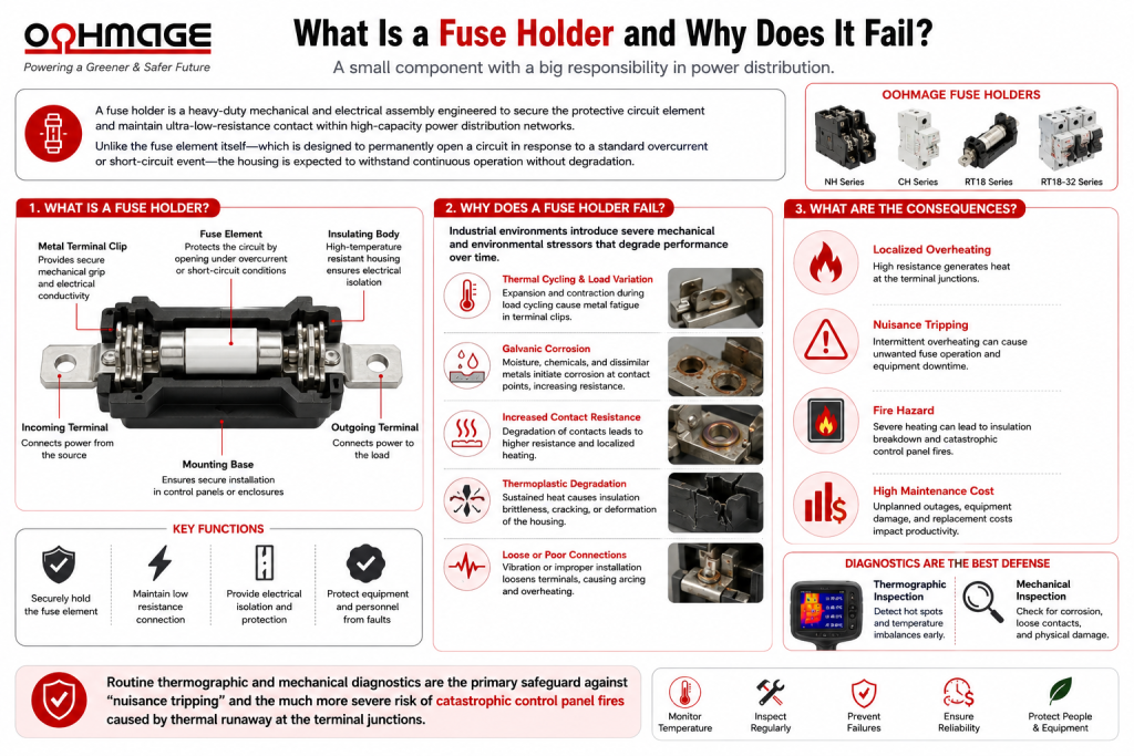
What Is a Fuse Holder and Why Does It Fail?
A fuse holder is a heavy-duty mechanical and electrical assembly engineered to secure the protective circuit element and maintain ultra-low-resistance contact within high-capacity power distribution networks. Unlike the fuse element itself—which is designed to permanently open a circuit in response to a standard overcurrent or short-circuit event—the housing is expected to withstand continuous operation without degradation.
However, the reality of industrial environments introduces severe mechanical and environmental wear factors. Thermal expansion and contraction during load cycling induce metal fatigue in the terminal clips, while varying atmospheric conditions can initiate galvanic corrosion at the contact points. These degradations increase internal resistance, leading to localized heating. Consequently, routine thermographic and mechanical diagnostics serve as the primary safeguard against “nuisance tripping” and the much more severe risk of catastrophic control panel fires caused by thermal runaway at the terminal junctions.
Step-by-Step Diagnostics: How to Test an AC Fuse Holder
Pre-Test Safety and LOTO Procedures
Before opening any live industrial enclosures, safety is paramount. It is an absolute necessity to adhere strictly to site-specific Lockout/Tagout (LOTO) procedures. Furthermore, technicians must comply with NFPA 70E or IEC 61482 standards regarding Arc Flash Personal Protective Equipment (PPE). Diagnostic testing should only commence once appropriate boundaries have been established and arc-rated gear is utilized.
Sequential Diagnostic Workflow
To accurately test an AC fuse holder without compromising safety or data integrity, follow this systematic progression:
Zero Energy Verification: Systematically isolate the power source. Utilize a calibrated true-RMS multimeter to verify an absolute zero-voltage state across all incoming and outgoing terminals before any physical contact is made.
Mechanical Retention Assessment: Insert a standard gauge or a known-good dummy fuse to evaluate the dynamic clamping force of the metallic clips. Inadequate or highly variable tension indicates advanced metal fatigue, rendering the unit structurally compromised.
Micro-Ohm Resistance Testing: Perform a precision continuity check across the isolated holder using a digital low-resistance ohmmeter (DLRO). Resistance readings that exceed the manufacturer’s baseline specifications indicate internal galvanic corrosion, pitting, or compromised plating.
Millivolt Drop Testing (Load Analysis): Under controlled, safe re-energized conditions (and while wearing appropriate PPE), measure the voltage drop across the component while under load. A drop exceeding standard allowable thresholds confirms unacceptable internal resistance, dictating immediate replacement.
Identifying Thermal and Visual Anomalies
Non-destructive testing relies heavily on visual and thermal inspections. Infrared thermography is highly effective for detecting Delta-T (temperature difference) anomalies between phases; a significant temperature variance on one pole of a multiphase system is a leading indicator of terminal degradation.
Visually, technicians must inspect for carbon tracking (indicating micro-arcing), oxidation or discoloration on the retention clips, and thermoplastic embrittlement, where the protective housing becomes rigid, cracked, or deformed due to sustained localized heating.
Decoding Amp Fuse Holder Specifications for Replacement
Calculating Current and Derating Factors
When specifying an amp fuse holder for replacement, electrical engineers must carefully match the continuous operating current of the circuit to the replacement’s rated capacity. However, nominal ratings are not absolute. It is critical to apply ambient temperature derating factors, particularly for densely packed, high-heat industrial enclosures. If derating curves are ignored, an enclosure running at elevated temperatures will push the component beyond its thermal limits, leading to premature melting of the housing even if the current remains below the nominal limit.
Voltage Ratings and AC vs. DC Requirements
The replacement must match or exceed the maximum system voltage. More importantly, engineers must strictly avoid the dangerous cross-application of AC and DC-rated housings.
Alternating current features a zero-crossing phenomenon—where the voltage drops to zero 100 or 120 times per second—which naturally helps extinguish electrical arcs. Direct current does not possess this characteristic; a DC arc is sustained and much harder to break. Therefore, DC components require specific internal dielectric spacing, rapid arc-quenching mechanisms, and specialized materials. Applying an AC-rated housing in a DC circuit risks sustained arcing, rapid material breakdown, and severe fire hazards.
Best Practices for Component Installation and Commissioning
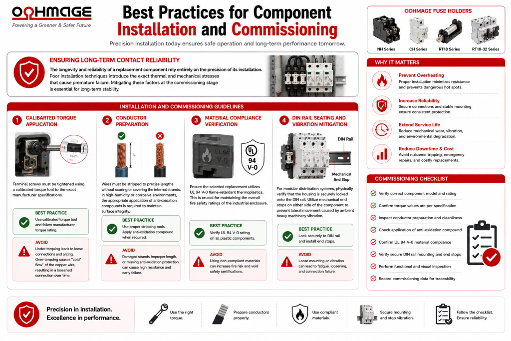
Ensuring Long-Term Contact Reliability
The longevity and reliability of a replacement component rely entirely on the precision of its installation. Poor installation techniques introduce the exact thermal and mechanical stresses that cause premature failure. Mitigating these factors at the commissioning stage is essential for long-term stability.
Installation and Commissioning Guidelines
Calibrated Torque Application: Terminal screws must be tightened using a calibrated torque tool to the exact manufacturer specifications. Under-torquing leads to loose connections and arcing, while over-torquing causes “cold flow” (deformation) of the copper wire, eventually resulting in a loosened connection over time.
Conductor Preparation: Wires must be stripped to precise lengths without scoring or severing the internal strands. In high-humidity or corrosive environments, the appropriate application of anti-oxidation compounds is required to maintain surface integrity.
Material Compliance Verification: Ensure the selected replacement utilizes UL 94 V-0 flame-retardant thermoplastics. This is crucial for maintaining the overall fire safety ratings of the industrial enclosure.
DIN Rail Seating and Vibration Mitigation: For modular distribution systems, physically verify that the housing is securely locked onto the DIN rail. Utilize mechanical end stops on either side of the component to prevent lateral movement caused by ambient heavy machinery vibration.
Final Thoughts
Maintaining industrial facility uptime hinges on the non-negotiable role of rigorous diagnostic testing and precise component specification. Treating protective housings as simple passive components ignores the reality of thermal cycling and mechanical fatigue. Electrical contractors and facility managers must prioritize the procurement of certified materials, adhere strictly to current derating calculations, and enforce proper torqueing protocols during installation.
For facilities looking to upgrade their power distribution networks, seamless integration begins with sourcing highly reliable, ISO-certified OEM panel components. We invite you to transition your procurement strategy by consulting with Oohmage’s engineering team for expertly engineered distribution solutions tailored to your exacting industrial requirements.
FAQs
What are the earliest visual and thermal signs that a fuse holder requires replacement?
Visually, the earliest signs include discoloration of the metal clips, hairline cracks in the plastic housing (embrittlement), and faint carbon tracking around the terminals. Thermally, an infrared camera will detect a Delta-T (temperature difference) anomaly, highlighting a localized hot spot at the junction point before visible melting occurs.
How does ambient panel temperature affect the derating curve of an amp fuse holder?
All protective components generate internal heat under load. If the ambient temperature inside the control panel is exceptionally high, the component cannot dissipate this heat effectively. Manufacturer derating curves dictate that as ambient temperature rises, the maximum allowable continuous current must be reduced (derated) to prevent the thermoplastic housing from exceeding its maximum thermal threshold and melting.
Why is it a safety violation to use an AC fuse holder in a direct current (DC) solar array?
AC power naturally drops to zero volts multiple times a second (zero-crossing), which inherently helps extinguish electrical arcs when a circuit opens. DC power provides a constant, continuous voltage without zero-crossings, making arcs significantly harder to extinguish. A component designed only for AC lacks the necessary arc-chutes, magnetic blowouts, or adequate dielectric spacing to break a DC arc, leading to sustained arcing, plasma generation, and catastrophic fire.
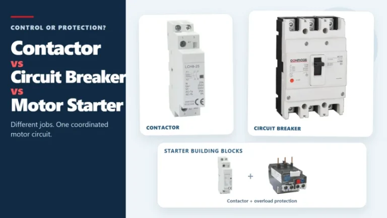
Figure 1. Contactors, circuit breakers, and motor starters solve different control and protection tasks. These three devices often appear in the same motor-control panel, but they solve different problems. A contactor handles frequent, remote, or automatic switching during normal operation. A circuit breaker interrupts abnormal current within its rated capability. A motor starter normally combines […]
A single-line diagram can look simple and still be difficult to read. One line may represent a multiphase circuit, a small symbol may stand for a major protective device, and a short label may carry the information that determines what equipment belongs downstream. The most reliable way to read a single-line diagram is to follow […]
Figure 1. Three-phase SPD selection starts with system facts, not the largest kA number. A three-phase surge protector should not be selected by the largest kA number on its label. First confirm the system voltage, whether a neutral is present, the earthing arrangement, the installation point, and the required SPD type. Then compare Uc, Up, […]