Molded Case Circuit Breaker (MCCB): What It Is, What It Contains, and How to Select One
Published: Author: Joanna
Introduction
Every industrial plant and large-scale power network relies heavily on reliable high-capacity electrical protection. These facilities continuously consume massive amounts of electricity to power heavy manufacturing lines, sprawling lighting grids, and centralized HVAC plants. A single protection failure might trigger catastrophic fires, halt production for days, or destroy irreplaceable equipment. Consequently, standard miniature breakers simply cannot keep pace with these extreme demands.
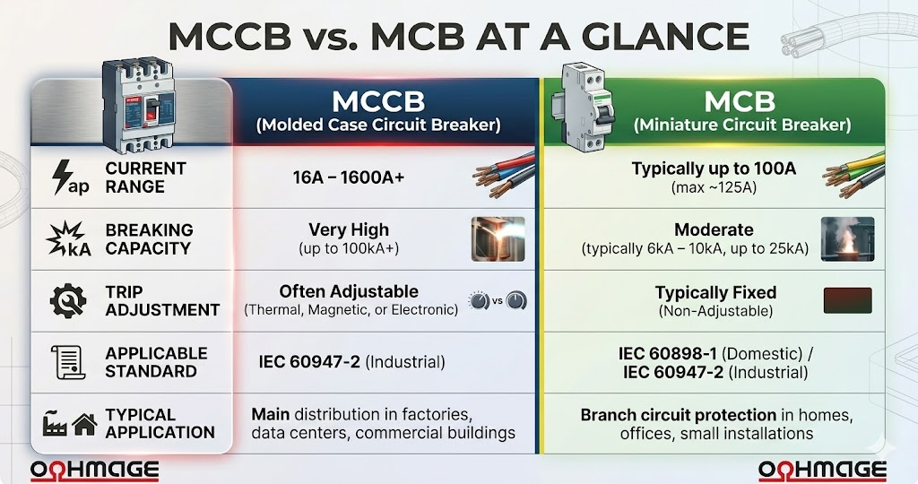
Miniature circuit breakers (MCBs) typically handle lower currents, whereas MCCBs manage higher ratings that range from tens to thousands of amps. Once electrical loads cross the 125A threshold, facilities urgently need a fundamentally different class of protective device. Therefore, this guide offers an objective, technical teardown of the Molded Case Circuit Breaker to help practitioners understand its value. From heavy-duty internal architecture to strict procurement criteria, the following sections provide actionable guidance for engineers and facility managers.
What Is a Molded Case Circuit Breaker (MCCB)?
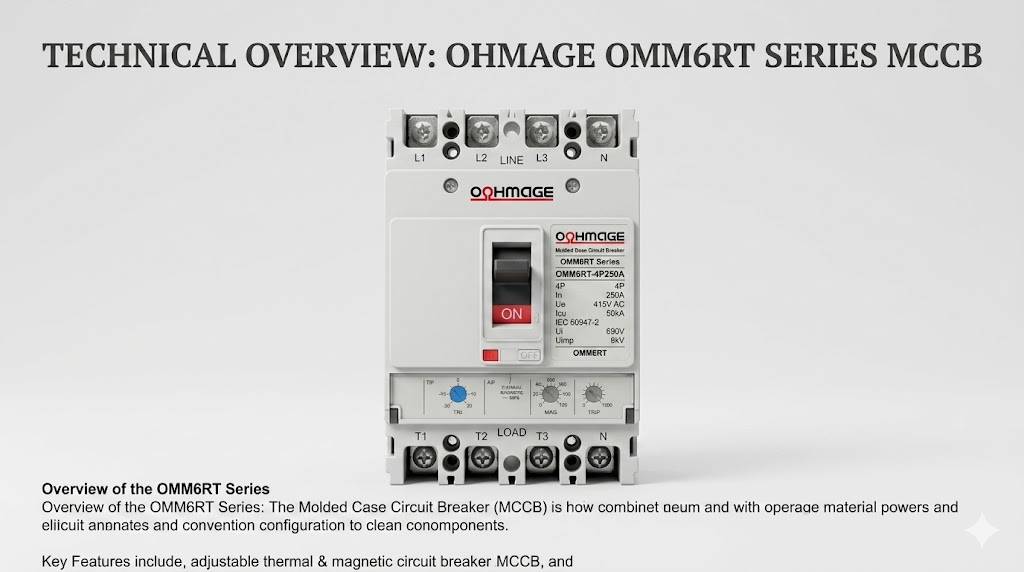
An MCCB operates as an industrial-grade protection device engineered to isolate electrical circuits automatically during severe short circuits or sustained overloads. Manufacturers name these devices after the molded insulating shell that encloses their internal components. This durable plastic case effectively protects users against electrical shock and guards the unit against environmental damage. The moment an electrical current exceeds safe thresholds, the device severs the power connection to prevent catastrophic equipment destruction.
The primary advantage of these units lies in their significantly higher current capacity. For instance, standard IEC-compliant MCCBs offer ratings from 16A all the way up to 1600A. Certain frame sizes push even further, protecting power distribution up to 1000V AC and 1500V DC with currents reaching 6300A. Ultimately, these robust devices serve as the absolute workhorse of heavy electrical infrastructure worldwide.
Unlike standard residential breakers, industrial applications require high breaking capacities and adjustable protection settings. Advanced units, such as the OMM6RT series, perfectly exemplify this engineering philosophy. They deliver reliable, customizable protection tailored for diverse facility requirements across complex global power grids.
What Does a Standard Molded Case Circuit Breaker Contain?
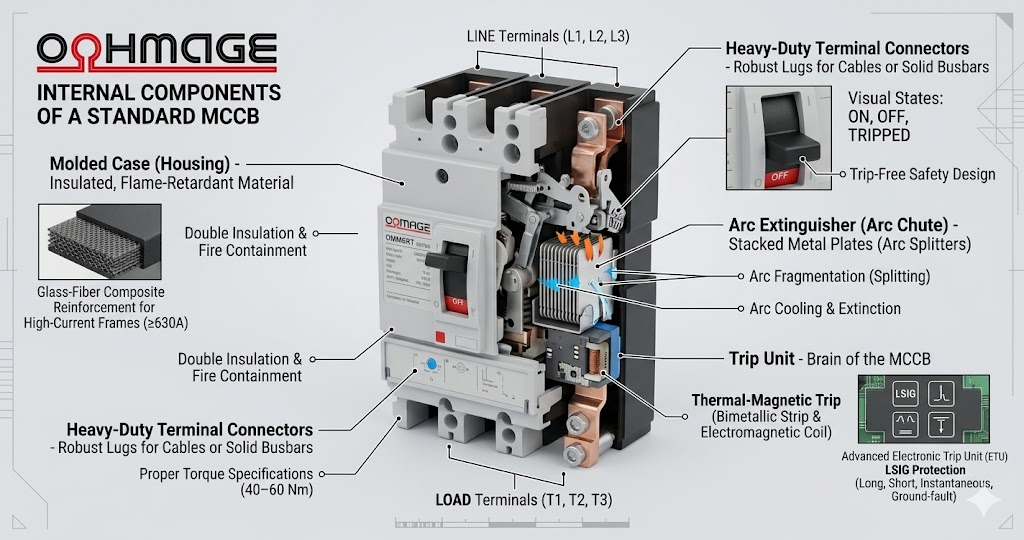
Understanding what does a standard molded case circuit breaker contain requires examining its internal components closely. Each highly specialized part plays a critical, synchronized role in maintaining absolute electrical safety.
The Molded Case (Housing)
The rigid outer shell is made of insulated material—often a rugged plastic or resin—that houses all internal parts, providing structural support and electrical insulation even in harsh environments. Typical materials include thermoset plastics, glass-polyester composites, and DMC (Dough Molding Compound). This housing delivers three vital functions: immense mechanical strength that keeps internal components aligned under severe stress, double insulation that protects operators from live conductors, and fire containment during internal arcing events.
For high-current frame sizes (630A and above), manufacturers reinforce the housing with glass-fiber composites to maintain rigidity under extreme thermal loads. The casing is not just a shell—it is an engineered safety barrier.
The Operating Mechanism
A mechanical linkage and toggle handle allows manual operation of the breaker—turning it on or off—and provides the force to open contacts during a trip. The mechanism includes springs and levers so that when a trip is triggered, the contacts snap open rapidly.
Three visual states appear on the toggle: ON, OFF, and TRIPPED. This immediate visual feedback accelerates troubleshooting during emergency response. More importantly, the mechanism incorporates a “trip-free” safety design. Even if an operator physically holds the toggle in the ON position, the contacts will still open during a fault. No human intervention can override this automatic protection—a feature that prevents catastrophic failure during live fault conditions.
The Arc Extinguisher (Arc Chute)
When contacts separate under a heavy fault, a violent plasma arc forms between them. Safely extinguishing this arc is the most mechanically demanding task the MCCB must perform.
The separation causes an electric arc, which is drawn into an arc chute—a stack of insulated metal plates that split and cool the arc quickly. The arc chute extinguishes the arc, allowing current flow to stop safely. This component is vital for arc control, preventing damage to the breaker when it interrupts high currents.
During breaking actions, the design and stability of the arc chute directly affect the overall performance of the circuit breaker. The guidance and dispersion of the arc are primarily handled by the arc chute. Manufacturers continue optimizing internal arc chute layouts to reduce localized heat concentration and improve arc extinction speed—particularly important for breakers rated above 50kA.
The Trip Unit (Thermal-Magnetic vs. Electronic)
The trip unit is the “brain” of the entire MCCB assembly—a sensing mechanism that detects abnormal current and triggers disconnection. Two distinct types dominate the market:
Thermal-Magnetic Trip Units combine two physical elements. Traditional MCCBs use a thermal-magnetic trip unit, combining two elements: one responding to heat (thermal) and one to magnetic force. The bimetallic strip handles slow overloads; the electromagnetic coil handles sudden short circuits. This proven design delivers reliable, maintenance-free protection for standard applications.
Electronic Trip Units (ETUs) replace physics with microprocessors. LSIG protection is an advanced protection feature available in electronic trip units of Air Circuit Breakers (ACBs) and high-end Molded Case Circuit Breakers (MCCBs). LSIG stands for: Long-time + Short-time + Instantaneous + Equipment Ground-fault Protection. Engineers can digitally program precise protection curves to match highly specific industrial loads—a capability thermal-magnetic units simply cannot offer.
Heavy-Duty Terminal Connectors
Robust internal lugs anchor thick cables or solid copper busbars securely to the breaker. Proper installation strictly requires mounting these connections with specific torque ratings, often between 40 and 60 Nm. Poorly torqued terminals create dangerous thermal bottlenecks, leading to localized overheating and devastating panel fires. Therefore, technicians should always follow the manufacturer’s torque specifications without exception.
How Does a Molded Case Circuit Breaker Work?
Two distinct internal mechanisms provide comprehensive defense by targeting different electrical fault profiles.
Thermal Overload Protection
The thermal element manages prolonged, moderate overloads through an inverse-time response. Inside the trip unit, a precision bimetallic strip carries the circuit current. The two metals expand at different rates under heat. As excess current flows, the strip gradually bends—slowly at first, then increasingly until it triggers the mechanical trip latch.
This inverse-time characteristic is critical: a slight overload (perhaps 120% of rated current) might take several minutes to trip, while a severe overload at 300% clears within seconds. The graduated response prevents nuisance tripping during normal transient fluctuations while still catching dangerous sustained overloads before cable insulation melts.
Instantaneous Short-Circuit Protection
A sudden, massive surge—such as a dead short circuit—demands an entirely different response. The electromagnetic coil located near the trip latch provides that response. When thousands of amperes surge through the coil during a fault, the resulting magnetic field forcefully pulls the trip armature in milliseconds.
There is virtually no intentional time delay. The contacts separate immediately, and the arc chute extinguishes the resulting plasma. This near-instantaneous reaction prevents catastrophic electrical fires, dangerous arc flashes, and explosive equipment failures on the factory floor.
MCCB vs. MCB: Understanding the Technical Differences
Selecting the wrong breaker type creates serious safety, compliance, and liability risks. Engineers must understand these strict dividing lines before specifying equipment.
Current Capacity and Interrupting Ratings
MCBs under IEC 60898-1 have current ratings from 6A to 125A, a maximum rated short-circuit capacity (Icn) of 25kA, and an impulse withstand voltage (Uimp) of 4kV. MCCBs operate in an entirely different performance envelope. IEC 60947-2 covers circuit breakers with voltage up to 1000V AC and 1500V DC, current ratings from 125A up to 6300A or more, and fault current handling sometimes up to 200kA.
The conclusion is straightforward: you cannot safely substitute an MCB where an MCCB belongs. Heavy industrial motors, large commercial power feeds, and main distribution panels require the higher ratings only an MCCB can deliver.
Adjustability and Customization
This distinction defines the MCCB’s engineering advantage. MCCBs typically use adjustable thermal/magnetic settings rather than fixed B/C/D curves. Engineers can manually dial in both the thermal overload threshold and the magnetic instantaneous pickup to match the exact load profile of the facility.
A typical adjustable MCCB offers these configurable parameters:
Thermal (long-time) pickup: 0.4–1.0× rated current (In)
Magnetic (instantaneous) pickup: 5–10× rated current (In)
Electronic units: Fully programmable LSIG curves with adjustable time delays
Ground-fault options: Selectable sensitivity for enhanced earth-leakage protection
MCBs offer fixed trip curves (B/C/D), compact footprint, and typically lower breaking capacity, governed by IEC 60898-1. They remain the correct choice for final branch circuits—but never for distribution feeders or heavy motor loads.
Key Factors When Selecting an MCCB
Choosing the right device involves far more than simply matching amperage to a specific load. Professionals should consider the following criteria to form a complete procurement checklist.
Rated Current (In) and Frame Size (Inm)
The Frame Size (Inm) determines the physical dimensions and the maximum current the breaker housing can handle (e.g., a 250A frame). The Rated Current (In) is the actual current value the breaker is set to carry (e.g., a 160A trip unit in a 250A frame).
The key principle: choose the smallest frame that meets both your In and Icu requirements. Oversizing wastes valuable panel space, inflates budgets, and rarely improves protection quality.
Ultimate vs. Service Short-Circuit Breaking Capacity (Icu vs. Ics)
These two ratings are perhaps the most misunderstood—and most critical—specifications on any MCCB datasheet.
Ultimate breaking capacity (Icu) defines the maximum short-circuit current that a circuit breaker can interrupt without damaging itself. It can be considered the upper limit for the short-circuit current it can safely handle.
Service breaking capacity (Ics) is the maximum short-circuit current the circuit breaker can safely break at least three times and still resume normal operation.
For critical applications (hospitals, data centers), ensure Ics = 100% of Icu. For standard applications, Ics = 50% or 75% of Icu is often acceptable. Always prioritize a high Ics-to-Icu ratio for mission-critical installations where post-fault replacement downtime is unacceptable.
Number of Poles
Pole configuration must match the electrical network architecture:
1-Pole and 2-Pole — Single-phase circuits, limited to light commercial and residential incoming protection.
3-Pole (L1, L2, L3) — Standard for three-phase industrial networks, protecting all three active conductors.
4-Pole (L1, L2, L3, N) — Necessary when the neutral is distributed and high harmonic currents are expected (common in TN-S systems with non-linear loads).
Switching Neutral — Some 4-pole variants switch the neutral independently, required in certain generator changeover applications.
Most heavy three-phase industrial installations require 3-pole MCCBs at minimum. Always verify the network earthing system (TN-S, TN-C-S, TT, or IT) before specifying the pole count.
International Compliance
IEC 60947-2 is the international standard that defines performance requirements for low-voltage circuit breakers, including all MCCBs. When you see “IEC 60947-2” marked on a breaker nameplate, it confirms the device has been tested and certified to meet specific electrical, mechanical, and safety criteria.
The IEC/EN 60947-2 standard applies to circuit breakers used mainly in industrial applications where only instructed people have access. All circuit breakers should be conformity assessed and certified compliant in independent, highly reputed third-party laboratories. The standard sets the conformity tests—very close to operating conditions—that circuit breakers should undergo. Purchasing non-compliant equipment creates massive legal liability and guarantees premature facility failures.
Real-World Industrial Applications
These powerful devices protect critical infrastructure across virtually every heavy industry globally.
Main Distribution Boards (MDBs)
At the service entrance of any commercial building or factory, the main incomer MCCB acts as the primary safety barrier between the utility supply and the facility’s internal distribution network. Large-frame units (630A–1600A) receive raw high-amperage power directly from the utility transformer and distribute it safely to downstream secondary panels throughout the building.
A properly rated main MCCB can isolate the entire facility during upstream faults, protecting every downstream circuit simultaneously. Specifying a unit with adjustable trip settings at this critical point enables future-proof coordination as load profiles evolve.
Heavy Motor Protection
Large industrial motors draw massive inrush currents during startup, typically reaching 6 to 8 times their rated full-load current. Fixed-trip breakers frequently experience nuisance tripping under these heavy conditions, halting production repeatedly. Breakers with adjustable magnetic pickup thresholds solve this issue elegantly. Common applications include protecting large HVAC compressors, heavy-duty conveyor belts, and main power feeds for CNC machining centers.
Final Thoughts
The MCCB firmly occupies a non-negotiable position in every industrial and large commercial power system. It protects expensive capital assets, such as transformers and generators, from the destructive consequences of severe overloads. Facility uptime depends directly on carefully selecting units that match the exact electrical environment.
Engineers should always prioritize adjustable trip units to maintain future flexibility as facility loads evolve. Additionally, buyers must scrutinize the Ics rating rather than just relying on the headline Icu figure. Units that remain fully operational through repeated service-level events deliver significantly greater long-term value. The oohmage engineering team gladly offers technical consultations for projects requiring globally certified, adjustable protection solutions.
FAQs
Can an MCCB be used in a residential setting?
Yes, but only in limited scenarios. MCCBs occasionally serve as the main incoming isolation breaker for very large homes with substantial electrical demands—multiple EV chargers, heavy electric heating systems, or pool equipment. However, the IEC/EN 60898-1 standard applies to circuit breakers for overcurrent protection in households and similar installations, and these breakers are designed to be operated by uninstructed people without the need for maintenance. Standard residential branch circuits should still rely on MCBs. An MCCB at the main service panel is acceptable only when installed and maintained by qualified electricians.
What is the difference between Icu and Ics?
Icu (Ultimate Breaking Capacity) defines the maximum short-circuit current a circuit breaker can interrupt without damaging itself. After clearing a fault at its Icu limit, the breaker may require inspection or replacement. Ics (Service Breaking Capacity) is the maximum short-circuit current the breaker can safely break at least three times and still resume normal operation. Always verify Ics at the actual prospective short-circuit level of your installation—this determines whether the breaker survives repeated service events or needs replacement after a single major fault.
How do you test if a Molded Case Circuit Breaker is functioning correctly?
Professional testing goes beyond simply pressing the built-in test button (which only verifies mechanical trip function). Comprehensive verification requires secondary injection testing: specialized equipment injects controlled current through the breaker poles, and technicians compare actual trip times against the manufacturer’s published time-current curves. Many industrial facilities perform annual trip-time testing and conduct contact resistance checks every 3–5 years to ensure ongoing reliability and compliance with maintenance schedules.
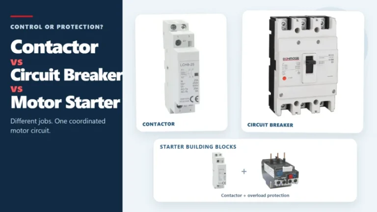
Figure 1. Contactors, circuit breakers, and motor starters solve different control and protection tasks. These three devices often appear in the same motor-control panel, but they solve different problems. A contactor handles frequent, remote, or automatic switching during normal operation. A circuit breaker interrupts abnormal current within its rated capability. A motor starter normally combines […]
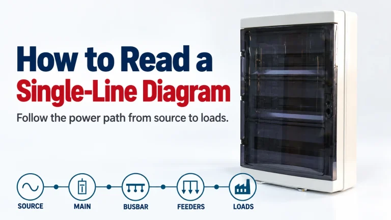
A single-line diagram can look simple and still be difficult to read. One line may represent a multiphase circuit, a small symbol may stand for a major protective device, and a short label may carry the information that determines what equipment belongs downstream. The most reliable way to read a single-line diagram is to follow […]
Figure 1. Three-phase SPD selection starts with system facts, not the largest kA number. A three-phase surge protector should not be selected by the largest kA number on its label. First confirm the system voltage, whether a neutral is present, the earthing arrangement, the installation point, and the required SPD type. Then compare Uc, Up, […]