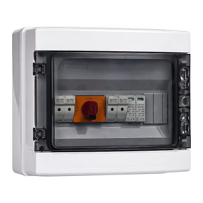
Схема подключения и компоненты солнечной соединительной коробки
Опубликовано: Автор: Конор
Что такое солнечный соединительный блок?
In PV systems, a солнечный соединительный блок brings selected photovoltaic (PV) string circuits into a defined output arrangement and can house protection, isolation or monitoring equipment. Whether a separate box is needed depends on the inverter inputs and the project design.
For buyers, a clear combiner box drawing makes string grouping, component ratings and inverter compatibility easier to check before ordering.
This guide explains common components and how to review a DC PV combiner box diagram. It is a design-reading reference; installation and commissioning require qualified personnel, the equipment instructions and the applicable project requirements.
Краткий обзор схемы подключения: На типичной схеме подключения фотоэлектрической распределительной коробки показаны входы для солнечных цепочек, предохранители или автоматические выключатели постоянного тока, шины, заземление, устройство защиты от перенапряжений и один или несколько выходов на инвертор. Перед тем как выбрать комбинированная коробка, уточните количество струн, напряжение в системе, номинальный ток, устройства защиты и требования к корпусу.
Прочитайте связанные статьи, чтобы узнать больше о соединительных коробках для солнечных батарей:
Почему схемы подключения солнечных комбайнерных блоков имеют такое большое значение
A wiring diagram helps reviewers trace connections, protection and output grouping. Check that it identifies the equipment model and drawing revision. A conceptual diagram alone does not establish that an installation is safe or compliant.
Компоненты коробки объединения фотоэлектрических цепей постоянного тока
Коробка объединения фотоэлектрических цепей постоянного тока, как правило, состоит из нескольких важных компонентов, которые в совокупности обеспечивают эффективную и безопасную работу вашей солнечной электростанции. Ниже приводится описание наиболее важных компонентов:
PV combiner box enclosure
Корпус представляет собой оболочку, в которой размещены все внутренние компоненты. Обычно он изготавливается из пластика или металла для защиты системы от воздействия внешней среды, например, дождя, пыли и чрезмерного солнечного излучения. Этот корпус защищает систему от повреждений и потери работоспособности с течением времени.
Предохранители и автоматические выключатели
Fuses and circuit breakers are important parts of overcurrent protection. They must be selected and coordinated with the PV string and the inverter to interrupt fault or reverse current within their declared voltage, current, and breaking-capacity ratings. A Плавикий предохранитель постоянного тока typically needs to be replaced after it is blown, whereas circuit breakers can be reset once the cause of the trip has been identified and cleared.
Шины и клеммные колодки
Busbars provide conductive paths for the circuits assigned to them. Terminal blocks provide conductor connection points with conductive contacts and insulating supports. Their current, voltage, conductor-size and environmental ratings must match the design; the housing material alone does not establish suitability.
Заземление
Earthing and equipotential bonding must follow the equipment instructions and the project design. The drawing should identify the protective connections required for exposed conductive parts. Do not assume that the PV negative conductor and protective earth are interchangeable.
Устройства защиты от перенапряжения (SPD)
PV-rated surge protective devices limit transient overvoltages according to their declared application and connection arrangement. Check the specified PV voltage, protection configuration and earthing connections against the product instructions.
Что касается каскада защиты от перенапряжений в конструкции фотоэлектрического комбайнера, ознакомьтесь с OOHMAGE устройства защиты от перенапряжения and confirm the PV DC-side voltage, Type 1+2 or Type 2 requirements, pole configuration and discharge-current ratings before quotation. Surge protection on the AC side belongs to the AC installation rather than to the combiner box.
Схемы подключения могут быть представлены в двух основных форматах: иллюстрированный и схема.
Иллюстрированные схемы
На схеме с иллюстрациями используются наглядные изображения и представления компонентов, что делает её чрезвычайно понятной даже для тех, кто имеет небольшой опыт работы с электрическими системами.
A pictorial diagram illustrates the arrangement of the equipment shown. Use the supplied model-specific drawing and terminal markings to confirm actual connections.
Схемные диаграммы
На схематическом чертеже, однако, для обозначения аппаратных компонентов и проводки используются символы. Этот тип чертежей носит более технический характер и предполагает некоторое знакомство с электрическими символами и принципами работы системы. Однако для экспертов и практикующих специалистов схематические чертежи оказываются наиболее полезными.
Как читать и интерпретировать электрическую схему
Умение читать электрическую схему солнечной соединительной коробки является необходимым навыком для любого специалиста, занимающегося монтажом или техническим обслуживанием солнечных систем. На схеме, как правило, отображаются:
Подключения входов и выходов: На рисунке показано, как провода от солнечных панелей подключаются к соединительной коробке, а затем — к инвертору или аккумулятору.
Защита цепей: На схематических диаграммах обычно указывается, где Выключатели постоянного тока а предохранители расположены относительно системы.
Точки заземления: Для обеспечения безопасности специально указаны обозначения точек заземления.
Распространенные символы на электрических схемах
Use the drawing legend to identify fuses, circuit breakers, disconnectors, busbars and protective-earth connections. Confirm unfamiliar symbols against the referenced drawing standard; do not infer a device’s switching or isolation capability from its symbol alone.
Before Installation: Review the Drawing and Documents
Use the drawing to resolve specification questions before work begins. The checklist below supports design and procurement review; it is not an installation sequence.
The third-party video illustrates one arrangement. Its connections are not a universal wiring procedure for other equipment or projects.
Confirm the Equipment and Output Groups
Identify the exact combiner model, drawing revision, PV string inputs and inverter inputs. Check which circuits are combined and which remain separate for the intended MPPT arrangement. Do not assume all negative conductors belong on a common busbar.
Check Five Items Before Accepting the Drawing
Inputs and outputs: string count, circuit labels, output grouping and the intended inverter input arrangement.
Protection devices: fuse or breaker model, declared DC ratings and the protection arrangement required by the design.
Isolation boundaries: which disconnecting device controls each circuit and which parts may remain energized.
Equipment instructions: terminal identification, permitted conductors, connector compatibility and the manufacturer’s specified termination requirements.
Inspection and commissioning: the project test plan, responsible qualified personnel and the records required before handover.
Recognize the PV Voltage Hazard
PV modules can generate hazardous DC voltage whenever exposed to light. Switching off an inverter does not by itself establish that the array wiring is de-energized. Qualified personnel must follow the equipment-specific isolation and verification procedure. See the SMA safety guidance for an example of this hazard; its product-specific procedure must not be substituted for your equipment instructions.
Commissioning must follow the project inspection and test plan, including the required checks of protective connections, polarity, terminations and insulation. A general article cannot determine the sequence of electrical work.
Распространённые ошибки, которых следует избегать при подключении солнечной распределительной коробки
Incorrect polarity or circuit grouping: compare the circuit labels and positive/negative paths with the approved drawing and inverter input arrangement.
Undersized conductors can overheat and create excessive voltage drop. Cable selection requires the circuit design current, installation conditions, applicable correction factors and equipment terminal limits.
Неправильные методы заземления: Poor grounding can increase the risk of electric shock or fire. Follow the equipment manufacturer’s instructions and the approved project design when selecting and installing grounding and bonding arrangements.
При работе с соединительными коробками для солнечных батарей возникают и другие проблемы. Ознакомьтесь с этой статьёй:
Рекомендации по подключению солнечных соединительных коробок
Cable sizing: review design current, routing, ambient conditions, grouping, allowable voltage drop, insulation rating and terminal compatibility. A string count or a small/large system label is insufficient to select a conductor size.
Герметизация и защита от атмосферных воздействий: For external installations, check that all inlet and outlet points are closed to the enclosure’s declared ingress-protection (IP) rating, and confirm that rating against the product instructions.
Маркировка и обозначение соединений: Промаркируйте все компоненты и провода в соединительной коробке. Это упростит обслуживание системы в будущем и позволит любому специалисту, работающему с системой, без труда распознавать отдельные компоненты.
Заключение
A useful combiner box diagram connects the equipment list to the string arrangement, protection strategy and inverter inputs. Review those items together before ordering or installation.
Send your string count, maximum system voltage, circuit currents, output grouping and installation environment with your enquiry. This gives the supplier a clear basis for checking the proposed configuration and identifying missing information.
О компании OOHMAGE
OOHMAGE manufactures and supplies low-voltage electrical products for overseas distributors, project buyers and professional customers.
OOHMAGE supports product selection, OEM/ODM packaging, outgoing inspection and export order coordination according to the confirmed product and order requirements.
Certification and technical document support can be provided according to the confirmed product series and order requirements. Свяжитесь с нами with your application and product requirements.
Часто задаваемые вопросы
Как подключить распределительную коробку для фотоэлектрической системы постоянного тока?
There is no universal connection sequence for every DC PV combiner box. The installer must follow the approved model-specific drawing and equipment instructions. For design review, identify string inputs, protection, output grouping, earthing and the intended inverter inputs before accepting the drawing.
Как читать схему подключения солнечной распределительной коробки?
Чтобы разобраться в схеме подключения солнечного комбайнерного блока, сначала определите входные и выходные клеммы каждой цепочки солнечных панелей.
На схеме будет показано электрические защитные устройства (например, предохранители или автоматические выключатели), соединения шин и маршруты прокладки проводов к положительным и отрицательным клеммам. Знание основных электрических символов позволит вам правильно читать схему.
Как выбрать сечение провода для соединительной коробки солнечной системы?
Select conductor size from the electrical design and installation conditions, including circuit current, temperature, grouping, voltage drop and terminal limits.
Do not select a fixed AWG size solely from whether a PV system is described as small or large. Use the project cable calculation and the applicable equipment instructions.
Можно ли использовать солнечный соединительный блок как для систем постоянного, так и переменного тока?
A solar combiner box is a DC-side assembly used to combine outputs from multiple PV strings before the inverter. Where AC outputs must be combined downstream of string inverters, use a separate AC-side combiner or distribution assembly with ratings and protection suitable for that duty. Do not treat AC and DC combiner assemblies as interchangeable.
AC and DC combiner assemblies have different duties and component requirements. Do not assume an assembly is interchangeable between AC and DC applications.
В чём заключается разница между солнечной соединительной коробкой и распределительной коробкой?
Соединительная коробка солнечной системы используется для объединения нескольких цепочек солнечных панелей в одну выходную цепь, как правило, перед подачей постоянного тока на инвертор. Она оснащена защитными устройствами, такими как предохранители или автоматические выключатели.
Junction boxes are also used in photovoltaic systems, including on PV modules. The useful distinction is function: a string combiner provides the input/output arrangement and protection specified for the array, while a junction box provides the connections for its particular application.
Указание в вашем предложении только “коробка для объединения солнечных батарей” далеко не достаточно. Что именно должно подключаться к этой коробке? Фотоэлектрическая цепь или выход инвертора? Они предназначены для разных задач. Вопросы цены и размера корпуса можно рассмотреть на более позднем этапе. Главный приоритет — то, что подключается к входу. Если говорить точнее, то это комбайнер постоянного тока […]
Что такое соединительная коробка? В солнечных энергетических системах фотоэлектрическая соединительная коробка играет ключевую роль. Она упрощает подключение нескольких массивов солнечных панелей к инвертору. Она обеспечивает эффективное управление мощностью, безопасность и возможность расширения системы. Чтобы выбрать подходящего поставщика фотоэлектрических соединительных коробок, необходимо иметь общее представление об этом продукте. Читайте дальше […]
Распределительный щит принимает входящее электропитание и организует распределение электроэнергии по выходным цепям. В зависимости от конструкции он может содержать главное коммутационное устройство, шины, автоматические выключатели, устройства защиты от остаточного тока, клеммы, внутреннюю проводку и маркировку, размещенные внутри соответствующего корпуса. Термины «распределительный щит», «распределительная коробка», «потребительский блок» и «панель» не являются взаимозаменяемыми […]
Мы используем файлы cookie для улучшения вашего пользовательского опыта, предоставления персонализированного контента и анализа посещаемости нашего сайта.